Rotor, Reluctance Machine and Method for Manufacturing the Rotor

a technology of reluctance machine and rotor core, which is applied in the direction of dynamo-electric machines, magnetic circuit rotating parts, and shape/form/construction of magnetic circuits, etc. it can solve the disadvantage of motor operation, increase the permeability along the q-axis, and influence the resistance ratio between the q-axis and the d-axis, so as to reduce the influence of the resistance ratio, increase the resistance of the web, and high degree of stability

Active Publication Date: 2017-08-17
KSB AG
View PDF6 Cites 4 Cited by
  • Summary
  • Abstract
  • Description
  • Claims
  • Application Information

AI Technical Summary

Benefits of technology

[0014]Ideally, all of the flux barriers which directly adjoin the outer rotor periphery are filled with the filler material at least in their peripheral region in order to achieve a high degree of stability of the rotor core and at the same time to cut out all of the web sections in the region of the flux barriers which adjoin the periphery in order to thereby allow an almost optimum resistance ratio between the q-axis and the d-axis.
[0015]It is likewise conceivable for one or more flux barriers to be divided into two or more by one or more webs. The design of these webs has, as already explained above, a disadvantageous effect on the properties of the permeability in the respective rotor portion. For this reason, the dimensions, in particular the thickness, of the webs formed should be kept as small as possible in order to restrict the influence on the resistance ratio as far as possible. However, when introducing the filler material used, in particular the aluminum or the aluminum alloy, a certain pressure can act on the webs, this possibly leading to the webs being damaged or broken under certain circumstances. Therefore, a suitable happy medium has to be found for the dimensions of the webs for optimum rotor operation. Against this background, a curved edge shape of the one or more webs has proven to be particularly advantageous. Curvature of the edges leads to increased resistance of the webs when the filler material is pressed in, but without widening of the webs and a resulting greater influence on the permeability of the rotor disadvantageously having to be accepted. An arcuate edge shape is particularly preferred.

Problems solved by technology

However, the structure and manufacture of conventional starting cages, comprising conductor bars and short-circuiting rings, have been comparatively complicated and expensive to date.
Since the webs are usually formed from the material of the rotor, that is to say a magnetically conductive material, preferably the lamination or a stacked laminated core, the design of said webs in the region of the q-axis has a disadvantageous effect on the magnetic resistance along the q-axis, that is to say this leads to an increase in the permeability along the q-axis.
As a result, influencing of the resistance ratio between the q-axis and d-axis, which is disadvantageous for motor operation, has to be accepted.
The design of these webs has, as already explained above, a disadvantageous effect on the properties of the permeability in the respective rotor portion.
However, when introducing the filler material used, in particular the aluminum or the aluminum alloy, a certain pressure can act on the webs, this possibly leading to the webs being damaged or broken under certain circumstances.
Curvature of the edges leads to increased resistance of the webs when the filler material is pressed in, but without widening of the webs and a resulting greater influence on the permeability of the rotor disadvantageously having to be accepted.

Method used


Image

  • Rotor, Reluctance Machine and Method for Manufacturing the Rotor
  • Rotor, Reluctance Machine and Method for Manufacturing the Rotor
  • Rotor, Reluctance Machine and Method for Manufacturing the Rotor

Examples


Embodiment Construction

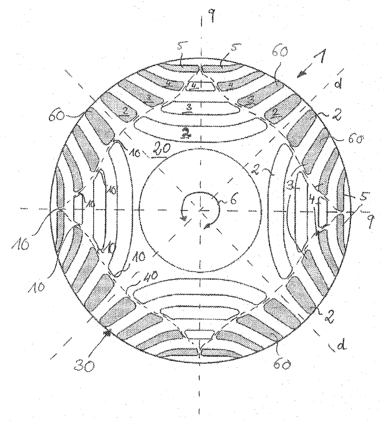
[0030]FIG. 1 shows a plan view of a rotor lamination 1 according to the invention. A large number of laminations 1 of this kind are stacked one on top of the other in an axial direction, that is to say along the rotation axis 6, for the construction of the rotor according to the invention. In order to simplify the illustration, the stator is not shown. The rotor lamination 1 has a plurality of cutouts 2, 3, 4, 5, which take on the function of flux barriers and the arrangement of which forms a four-pole rotor, the magnetic flux of said rotor being inhibited in the regions with the flux barriers 2, 3, 4, 5. The region with high magnetic conductivity is generally identified as the d-axis, and the region of lower magnetic conductivity is generally identified as the q-axis. The assembled laminated core is mounted on a rotor shaft, not illustrated. The arrangement of the individual flux barriers 2, 3, 4, 5 is based on the technical teaching of U.S. Pat. No. 5,818,140, to which reference i...


PUM


Abstract

A rotor for a reluctance machine and a method of producing a rotor for a reluctance machine is provided. The rotor is formed as a soft magnetic element which is cylindrical in shape. The soft magnetic element has recesses for forming flux barriers, one or more flux barriers being at least partially filled with a filler material, and the filler material of said flux barriers extending up to the rotor periphery and forming part of the rotor periphery.

Description

[0001]This application is a National Stage of PCT International Application No. PCT / EP2015 / 067908, filed Aug. 4, 2015, which claims priority under 35 U.S.C. §119 from German Patent Application No. 10 2014 215 304.2, filed Aug. 4, 2014, the entire disclosures of which are herein expressly incorporated by reference.BACKGROUND AND SUMMARY OF THE INVENTION[0002]The invention relates to a rotor for a reluctance machine comprising a cylindrical soft-magnetic element, wherein the soft-magnetic element has cutouts for forming flux barriers. The invention further relates to a reluctance machine having a corresponding rotor and also to a method for manufacturing a rotor of this kind.[0003]Rotors for synchronous reluctance machines are usually equipped with a cylindrical soft-magnetic element which is arranged coaxially on the rotor axis. In order to form at least one pole pair or gap pair, the soft-magnetic element comprises flux-conducting and flux-blocking portions, which differ from one an...

Claims


Application Information

Patent Timeline
Patent Type & Authority Applications(United States)
IPC IPC(8): H02K1/24H02K19/02H02K15/00
CPCH02K1/246H02K19/02H02K15/0012H02K19/14
Inventor GONTERMANN, DANIELJANJIC, BORISKOENEN, MICHAELSCHAAB, JOCHENSCHUNK, AXEL
Owner KSB AG
Why Eureka
Try Eureka