An energy carrier system for a vehicle

a technology of energy carrier and vehicle, which is applied in the direction of battery/fuel cell control arrangement, electrochemical generator, battery/cell propulsion, etc., can solve the problems of lubrication and recapturing of particles from exhaust flow, and it is difficult to achieve a complete reduction/oxidation of all particles in practice, so as to reduce fossil fuel consumption, reduce carbon dioxide emissions, and reduce the effect of fossil fuel consumption

Inactive Publication Date: 2017-08-10
VOLVO LASTVAGNAR AB
View PDF3 Cites 0 Cited by
  • Summary
  • Abstract
  • Description
  • Claims
  • Application Information

AI Technical Summary

Benefits of technology

[0002]There is a multitude of different fuel systems used today for land vehicles. The most commonly used fuel system today is probably liquid fuel systems based on a carbonaceous fuel, e.g. petrol or diesel. The fuel is used by an Internal Combustion Engine (ICE) in order to propel a vehicle. However, there is a desire to change from using fossil fuel to renewable energy sources in order to reduce the carbon dioxide emissions. One way of reducing the fossil fuel consumption is to replace the liquid fossil fuel for renewable fuels, e.g. methanol from fast growing energy woods may be used as a replacement fuel. Still another attempt to reduce the fossil fuel consumption is to use electric power systems in which an Electric Motor (EM) is used as an alternative or a complement to an ICE. A major drawback of electrical propulsion system is the ability to provide an energy storage which may provide enough energy for travelling a desired distance. In rough numbers, the energy density from liquid carbonaceous fuel such as petrol or diesel is of a magnitude at least 10 times higher than for an electric battery, i.e. the amount of useful energy per weight unit. Hence, there is a desire to provide an energy carrier which may have a higher energy density and may work efficiently in a land vehicle. One known fuel system which could be used is metal particles which by changing its oxidation state may release energy and produce electricity. An advantage with this fuel system is that it constitutes an energy carrier which has energy storage / density similar to the energy density of liquid HC fuel, such as gasoline or diesel. The energy storage capability is dependent on what type of metal powder is used, but it's for a number of metals possible to reach an energy storage density for 20-50 MJ / kg, if the full potential could be utilized. The other main merit with this system is that it is possible and plausible to have a relatively high total energy efficiency from charging electric energy to released electric energy of about 45% (about 67%*67% for charging and discharging the system). This is a lower efficiency in comparison with modern batteries that may have a corresponding efficiency of about 80%, but with the essential difference that the energy storage density metal powder is almost two orders of magnitude higher than compared with modern battery technology. A metal powder energy carrier system may thus open up for possibilities to produce a vehicle fuel system which uses electricity from a source having a substantially lower weight per energy unit than battery based systems.
[0003]One metal powder fuel system is for example disclosed in US 2006 / 99472 where metal particles are used as energy carriers. This system thus has the advantage of providing a high density energy carrier having an energy density in the same magnitude as for fossil liquid fuel. However, there is a problem in providing such a system for vehicles today which in an efficient way may be refueled and used on a daily basis for a reasonable cost. The present invention is directed to provide a system which may improve the cost efficiency and increase the usability of such a system to be based on a daily basis.
[0030]The main merit is as described above the high primary energy density but also that the innovative solution has an efficiency that is relatively high, when put in relation to the energy density of the system. One other merit with above described invention is that the particles are contained in a closed, sealed off system for the metal particles and they need not to be removed to be generated or reduced. Hence, the risk of releasing small fractions of nano-particles into the environment when they are oxidized is reduced compared to the alternative method of feeding the metal particles into a normal combustion chamber of an engine for rapid oxidation. In for example a normal reciprocal engine is this a drawback as well as problems with lubrication and recapturing of particles from the exhaust flow etc.BRIEF DESCRIPTION OF THE DRAWINGS

Problems solved by technology

A major drawback of electrical propulsion system is the ability to provide an energy storage which may provide enough energy for travelling a desired distance.
However, there is a problem in providing such a system for vehicles today which in an efficient way may be refueled and used on a daily basis for a reasonable cost.
However, it may be hard to achieve a complete reduction / oxidation of all particles in practice.
In for example a normal reciprocal engine is this a drawback as well as problems with lubrication and recapturing of particles from the exhaust flow etc.

Method used


Image

  • An energy carrier system for a vehicle
  • An energy carrier system for a vehicle
  • An energy carrier system for a vehicle

Examples


Embodiment Construction

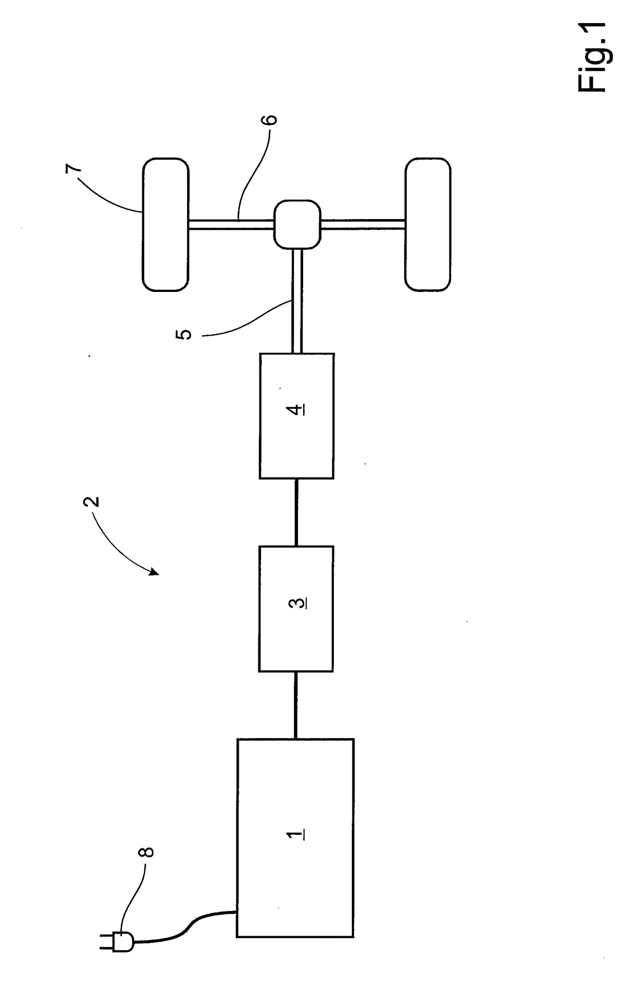
[0036]In FIG. 1 is disclosed a vehicle 2 provided with an Energy Carrier System (ECS) 1 according to the invention. The ECS 1 is designed to produce electric energy and is connected to an accumulator 3, e.g. a battery, for storage of the generated electrical energy. The accumulator 3 also comprises or is connected to Power Electronics Circuitry (PEC) for control of the electricity generating process (not shown). The accumulator 3 is connected to an Electric Motor (EM) 4 to be used as a propulsion unit for the vehicle. The EM 4 may be designed to work as a generator as well as a motor in order to be able to regenerate energy e.g. from braking of the vehicle 2. The EM 4 is further drivingly connected to a driven axle 6 comprising a pair of driven wheels 7 via a mechanical powertrain 5. Even though it is described the use of a driven axle 6 comprising a pair of driven wheels 7 could the electricity produced by the ECS 1 be used for any kind of electric propulsion system and the propuls...


PUM

PropertyMeasurementUnit
pressureaaaaaaaaaa
pressureaaaaaaaaaa
electric currentaaaaaaaaaa

Abstract

A device and a method for providing electricity to an electric motor for propulsion of a vehicle are provided. The method comprises the features of feeding Energy Carriers (EC) in the shape of particles having a first oxidation state (I) from a first container on board the vehicle to an Solid Oxide Fuel Cell (SOFC). The EC are reacted at the SOFC to change the oxidation state from the first oxidation (I) to the second oxidation state (II) while producing electric energy. The EC is thereafter fed from the SOFC to a second container on board the vehicle. A reversed reaction is enabled on board the vehicle, e.g., by applying a voltage to the SOFC to reverse the reaction, and the EC are reacted to change its oxidation state from its second oxidation state (II) back to its first oxidation state (I) before the EC is returned to the first container. A system for performing the method is also provided.

Description

BACKGROUND AND SUMMARY[0001]The invention relates to a fuel system for a land vehicle, e.g. trucks, buses, cars or construction equipment. The fuel system is directed to the use of metal powder or metal particles to be used as energy carriers in order to provide electrical power to vehicles.[0002]There is a multitude of different fuel systems used today for land vehicles. The most commonly used fuel system today is probably liquid fuel systems based on a carbonaceous fuel, e.g. petrol or diesel. The fuel is used by an Internal Combustion Engine (ICE) in order to propel a vehicle. However, there is a desire to change from using fossil fuel to renewable energy sources in order to reduce the carbon dioxide emissions. One way of reducing the fossil fuel consumption is to replace the liquid fossil fuel for renewable fuels, e.g. methanol from fast growing energy woods may be used as a replacement fuel. Still another attempt to reduce the fossil fuel consumption is to use electric power sy...

Claims


Application Information

Patent Timeline
Patent Type & Authority Applications(United States)
IPC IPC(8): H01M8/18H01M8/1246B60L11/18H01M8/04082
CPCB60L11/18H01M2250/20H01M8/1246H01M8/184H01M8/04201H01M2008/1293H01M8/225H01M12/08H01M8/04208B60L50/72B60L58/34B60L50/70Y02E60/50Y02T90/40Y02E60/10
Inventor LUNDGREN, STAFFAN
Owner VOLVO LASTVAGNAR AB
Why Eureka
Try Eureka