
Method for fabricating a semiconductor device

a semiconductor device and manufacturing method technology, applied in the field of semiconductor devices, can solve problems such as prior art methods

Active Publication Date: 2017-07-27
MICRON TECH INC
View PDF0 Cites 2 Cited by
  • Summary
  • Abstract
  • Description
  • Claims
  • Application Information

AI Technical Summary

Benefits of technology

This patent is about a new invention that has specific objectives. These objectives may become known to those working in the field of medical devices after reading the details of the preferred embodiment in the text. The invention is described in detail through drawings and other methods.

Problems solved by technology

However, the prior art method has some drawbacks, for example, copper extrusion on the exposed ends of the electrical through vias on the rear side of the silicon substrate.

Method used


Image

  • Method for fabricating a semiconductor device
  • Method for fabricating a semiconductor device
  • Method for fabricating a semiconductor device

Examples


Embodiment Construction

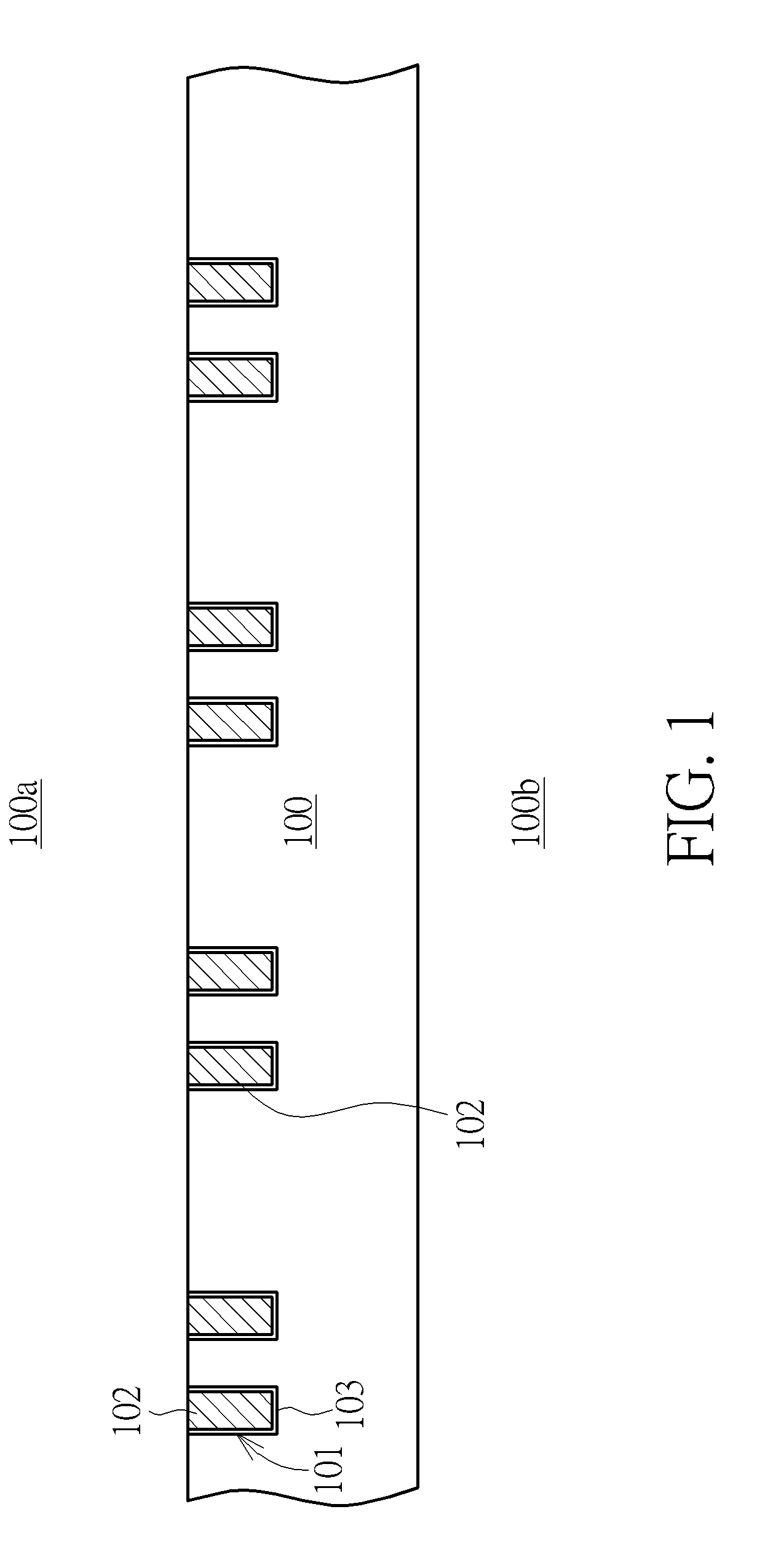
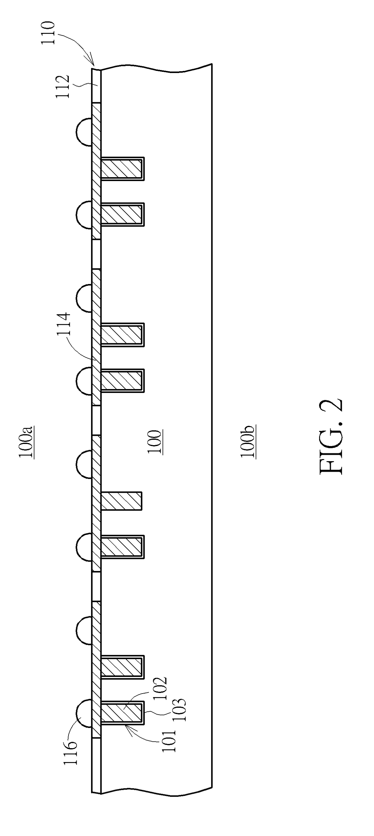
[0011]In the following detailed description of the invention, reference is made to the accompanying drawings, which form a part hereof, and in which is shown, by way of illustration, specific embodiments in which the invention may be practiced. These embodiments are described in sufficient detail to enable those skilled in the art to practice the invention. Other embodiments maybe utilized and structural changes may be made without departing from the scope of the present invention.

[0012]The following detailed description is, therefore, not to be taken in a limiting sense, and the scope of the present invention is defined only by the appended claims, along with the full scope of equivalents to which such claims are entitled. One or more implementations of the present invention will now be described with reference to the attached drawings, wherein like reference numerals are used to refer to like elements throughout, and wherein the illustrated structures are not necessarily drawn to ...


PUM


Abstract

A method of fabricating a semiconductor device. A wafer having a front side and a back side opposite to the front side is prepared. A plurality of through substrate vias (TSVs) is formed on the front side. A redistribution layer (RDL) is then formed on the TSVs. The wafer is bonded to a carrier. A wafer back side grinding process is performed to thin the wafer on the back side. An anneal process is performed to re-crystallize the TSVs. A chemical mechanical polishing (CMP) process is performed to polish the back side.

Description

BACKGROUND OF THE INVENTION[0001]1. Field of the Invention[0002]The present invention relates generally to a semiconductor device, and more particularly to a TSV interposer and a fabrication method thereof.[0003]2. Description of the Prior Art[0004]A through substrate via (TSV) interposer is a device with electrical through vias that is inserted between one or more integrated circuit chips and a mounting substrate. The electrical through vias allow the integrated circuit chips to be electrically connected to the mounting substrate.[0005]As known in the art, the electrical through vias are formed by providing holes in a front side of a silicon substrate, insulating the sidewall of the through holes, filling a conductor metal such as copper in the through holes by plating or the like, and then grinding the silicon substrate on its rear side to expose the other ends of the electrical through vias for further connection.[0006]However, the prior art method has some drawbacks, for example...

Claims


Application Information

Patent Timeline
IPC IPC(8): H01L21/768H01L21/306H01L23/00H01L21/683
CPCH01L21/76898H01L21/76883H01L21/6835H01L21/76831H01L2224/13024H01L24/11H01L2221/68327H01L2221/68381H01L21/30625H01L21/76877H01L2221/6834
Inventor LAI, CHING-HUASHIH, CHIEN-HUNGCHIU, TING-CHUNG
Owner MICRON TECH INC
Learn More