
Horizontal gate all around nanowire transistor bottom isolation

a technology of nanowire transistors and nanowires, applied in the field of semiconductor devices, can solve the problems of shorting the gate dielectric from electrode to substrate, affecting device performance, and difficulty in controlling the inadvertent etching of the recessed trenches under the nanowire channels, so as to prevent the etching of the trenches in the substra

Active Publication Date: 2017-06-22
GLOBALFOUNDRIES US INC
View PDF0 Cites 33 Cited by
  • Summary
  • Abstract
  • Description
  • Claims
  • Application Information

AI Technical Summary

Benefits of technology

This patent describes a method for making a type of MOSFET called GAA MOSFET. The method includes using a layer called ESEW as an etch stop barrier to prevent damage to the substrate during the manufacturing process. The ESEW layer also serves as an electric barrier to prevent shorts across the gate dielectric. The method includes steps of doping the substrate, adding a sacrificial layer, adding a channel layer, and patterning a fin. By selectively etching away the sacrificial layer, a nanowire is formed and the ESEW layer protects the substrate from damage. The technical effect of this method is to improve the reliability and performance of GAA MOSFETs.

Problems solved by technology

With constant down-scaling and increasingly demanding requirements to the speed and functionality of ultra-high density integrated circuits, conventional planar metal-oxide-semiconductor field effect transistors (MOSFETs) face increasing challenges with such issues as scaling of gate oxide thickness and electrostatic control of the gate electrode over the channel region.
Problematically however, it is difficult to control the inadvertent etching of the recessed trenches under the nanowire channels.
This uncontrolled etch introduces trench to trench variations and an undesired roughness at the bottoms of the trenches, which can detrimentally affect device performance.
Additionally, the thin gate dielectric deposition does not always sufficiently isolate the metal gate from the substrate, which can lead to shorts across the gate dielectric from electrode to substrate.

Method used


Image

  • Horizontal gate all around nanowire transistor bottom isolation
  • Horizontal gate all around nanowire transistor bottom isolation
  • Horizontal gate all around nanowire transistor bottom isolation

Examples


Embodiment Construction

[0023]Certain exemplary embodiments will now be described to provide an overall understanding of the principles of the structure, function, manufacture, and use of the methods, systems, and devices disclosed herein. One or more examples of these embodiments are illustrated in the accompanying drawings. Those skilled in the art will understand that the methods, systems, and devices specifically described herein and illustrated in the accompanying drawings are non-limiting exemplary embodiments and that the scope of the present invention is defined solely by the claims. The features illustrated or described in connection with one exemplary embodiment may be combined with the features of other embodiments. Such modifications and variations are intended to be included within the scope of the present invention.

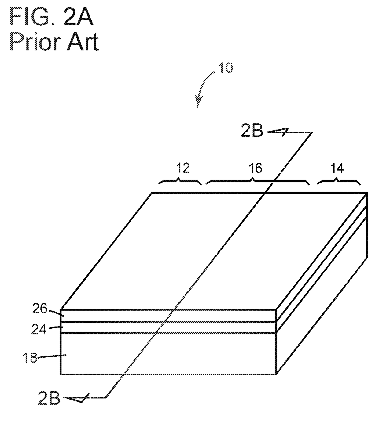
[0024]FIGS. 1-5 illustrate various exemplary embodiments of a prior art GAA MOSFET and methods of making the same.

[0025]Referring to FIG. 1, a simplistic perspective view of an exe...


PUM


Abstract

A method of forming a GAA MOSFET includes providing a substrate having source, drain and channel regions, the substrate doped with one of a p-type and an n-type dopant. Disposing an etch stop-electric well (ESEW) layer over the substrate, the ESEW layer doped with the other of the p-type and the n-type dopant. Disposing a sacrificial layer over the ESEW layer, the sacrificial layer doped with the same type dopant as the substrate. Disposing a channel layer over the sacrificial layer. Patterning a fin out of the ESEW layer, sacrificial layer and channel layer in the channel region. Selectively etching away only the sacrificial layer of the fin to form a nanowire from the channel layer of the fin while the ESEW layer of the fin functions as an etch stop barrier to prevent etching of trenches in the substrate.

Description

TECHNICAL FIELD[0001]The present invention relates to semiconductor devices and methods of fabricating the same. More specifically, the invention relates to various methods of forming nanowire channels in gate-all-around (GAA) MOSFETs.BACKGROUND[0002]With constant down-scaling and increasingly demanding requirements to the speed and functionality of ultra-high density integrated circuits, conventional planar metal-oxide-semiconductor field effect transistors (MOSFETs) face increasing challenges with such issues as scaling of gate oxide thickness and electrostatic control of the gate electrode over the channel region. Fin field effect transistors (FinFETs) have exhibited improved control over a planar gate MOSFET design by wrapping the gate electrode over three sides of a fin-shaped channel.[0003]GAA MOSFETs are similar to FinFETs but have the potential of even greater electrostatic control over the channel because the gate electrode completely surrounds the channel. In a GAA MOSFET,...

Claims


Application Information

Patent Timeline
Patent Type & Authority Applications(United States)
IPC IPC(8): H01L29/423H01L21/308H01L29/06H01L29/78H01L29/66
CPCH01L29/42392H01L29/785H01L21/3081H01L29/0673H01L29/66795H01L29/0669H01L29/66477H01L29/7848B82Y10/00H01L29/66439H01L29/775H01L29/1079H01L29/78696
Inventor PAWLAK, BARTLOMIEJ JAN
Owner GLOBALFOUNDRIES US INC
Learn More