High frequency multi-antenna transmitter(s)

a multi-antenna transmitter and high frequency technology, applied in the field of high frequency multi-antenna transmitters, modulating the transmission signal, can solve the problems of inability to transmit low frequency signals such as voice or video, difficulty in transmitting low frequency signals, and insufficient length of necessary antenna radiators

Active Publication Date: 2017-06-15
US SEC THE ARMY THE
View PDF5 Cites 8 Cited by
  • Summary
  • Abstract
  • Description
  • Claims
  • Application Information

AI Technical Summary

Benefits of technology

[0017]Unlike mixers, phase shifters introduce little power degradation or distortion into the signal. Consequently, the output from each phase shifter having a 10 watt input would be 90% of the power of the input signal or about 9 watts.
[0020]The transmitter may include a radio frequency signal source; and a splitter which receives an input signal from said signal source and divides said input signal into two input signals one for each of the two signal paths. In this configuration, the antennas may be located at the same location as the transmitter. In others, the transmitter may include a pair of radio frequency signal sources, each of the pair of signal sources providing an input signal to a respective one of the two signal paths. This permits the antennas to be located at different locations.

Problems solved by technology

Consequently, it is very difficult to transmit low frequency signals, such as voice or video, as electromagnetic waves at their original frequencies.
In order to do so, would render the necessary antenna radiators unacceptably long.
Although it is possible to amplify both the LO signal and both sideband signals for transmission from the appropriate antenna, to do so is very power inefficient.
This power inefficiency arises since each sideband signal contains the same modulation information and the LO signal contains no useful information at all.
However, this requires very narrow band filters to filter out the undesired signal.
Such filters, however, add distortion to the output signal.
While the previously known practice of using upconversion optionally followed by filtering of the upconverted signal has proven effective for relatively low frequency radio transmitters, i.e. radio transmitters transmitting at a frequency of less than 10 gigahertz, such radio communications transmitters have proven impractical for high frequency radio transmitters, i.e. radio transmitters in the range of 0.1 to 10 terahertz, for a number of different reasons.
First, solid-state frequency sources at such high frequencies, i.e. greater than 100 gigahertz, are necessarily low powered, typically generating 1 watt or less in power.
Otherwise, excessive distortion of the modulated sideband signal would occur.
However, to do so requires a very narrow band filter.
Such narrow band filters, particularly at high frequencies, are not only lossy but do not provide flat group delay.
Such narrow band filters also distort the signal and this distortion becomes worse as the filter bandwidth becomes narrower.
All these factors thus result in distortion of the signal desired for transmission as well as a very low output power for the modulated signal.
This, in turn, requires excessive amplification in order to reach an acceptable power level, e.g. a few watts, for practical applications.
For all the foregoing reasons, the use of RF mixers which mix IF sources with the LO mixer input, even when followed by frequency multipliers which also add distortion, results in excessive distortion and power loss for the RF signal.

Method used


Image

  • High frequency multi-antenna transmitter(s)
  • High frequency multi-antenna transmitter(s)
  • High frequency multi-antenna transmitter(s)

Examples


first embodiment

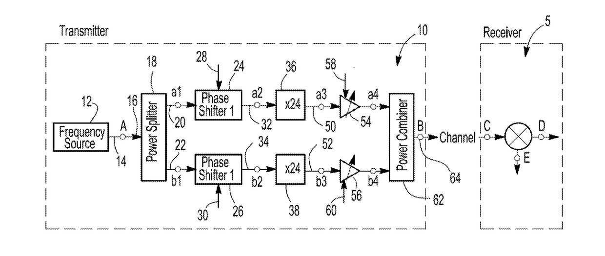
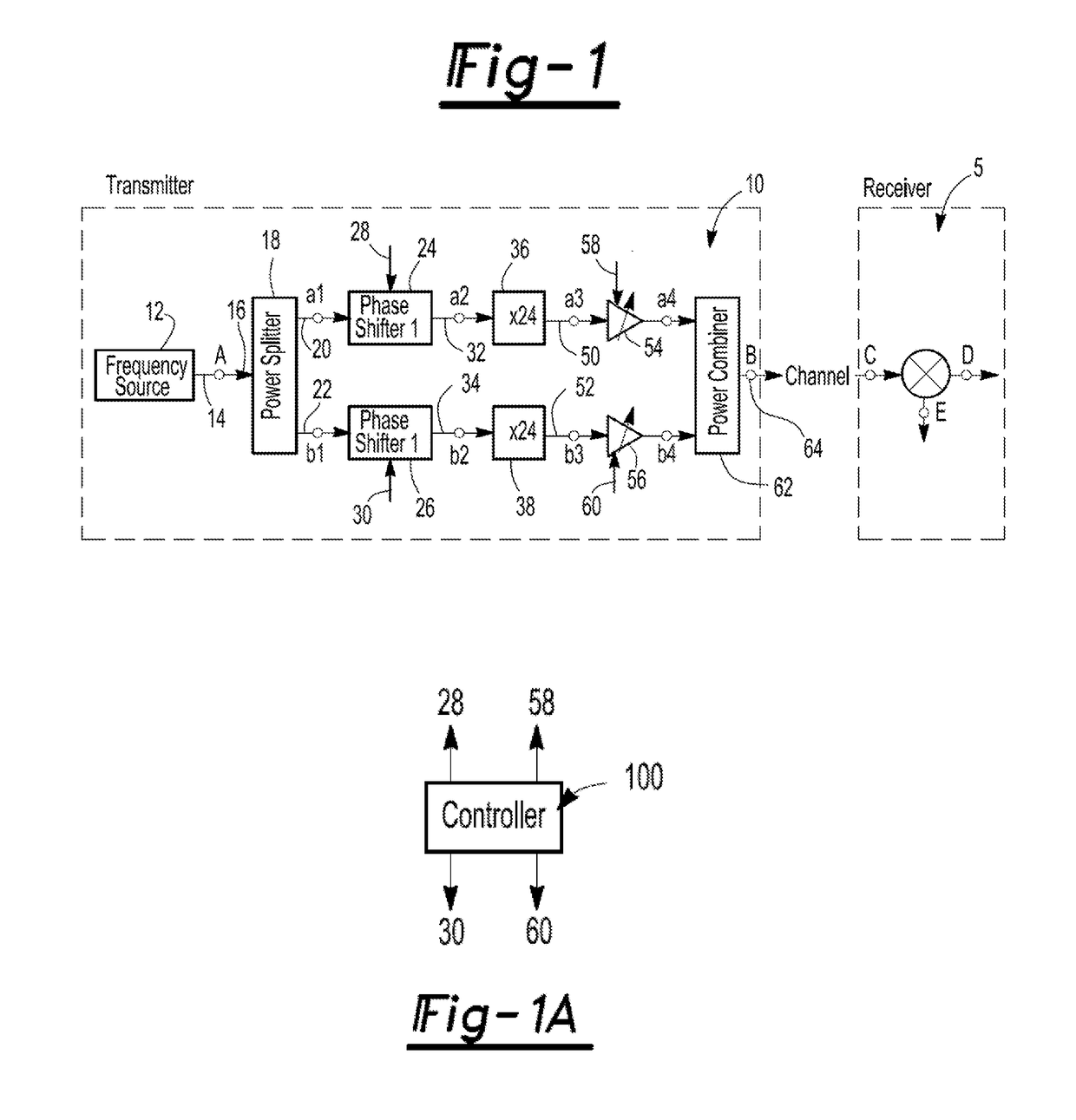
[0030]With reference first to FIG. 1, a block diagrammatic view illustrating a first embodiment radio frequency transmitter 10 is shown. The transmitter 10 is used in conjunction with a receiver 5 also illustrated in FIG. 1. The receiver 5 may be any conventional RF receiving device.

[0031]The transmitted 10 may be configured as high frequency transmitter in some embodiments. As used herein, the term “high frequency transmitter” shall mean a radio frequency transmitter transmitting at a frequency range in excess of 10 gigahertz and typically in the range of 0.1 terahertz to 10 terahertz. The use of high frequency provides many benefits over lower frequency communications. First, due to high frequency, the transmitted signal propagates in laser-like beams. Hence, communications can be very secure. Additionally, the high frequency opens the door to very broadband (e.g., tens of gigabits per second) communications. Also, a number of chemical and bio agents have resonances at high freque...

example 1 (fig.2a)

Example 1 (FIG. 2A)

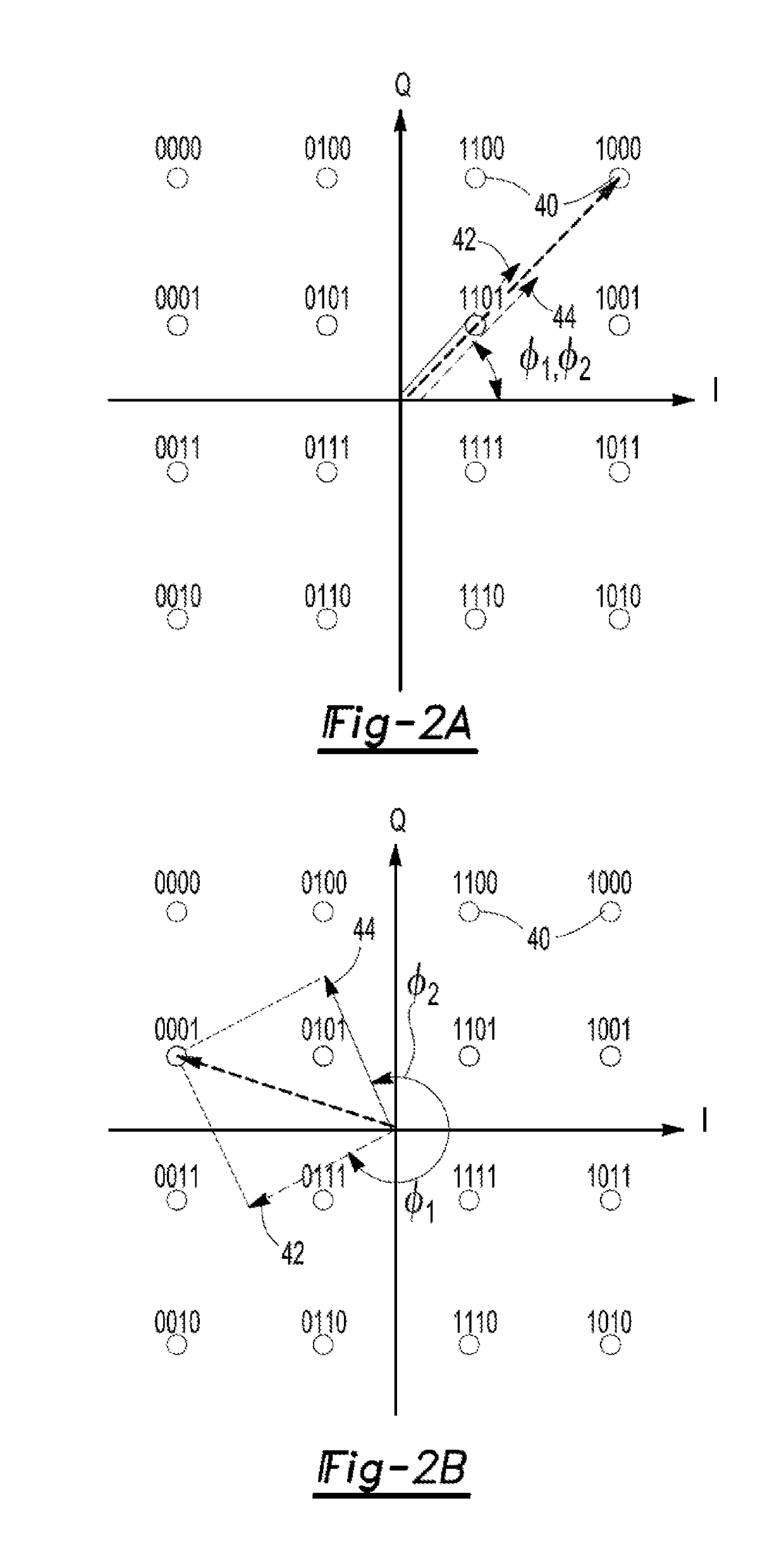
[0053]Suppose we would like to transmit symbol a 16QAM signal and suppose the maximum I amplitude, and Q amplitude is 3. The maximum amplitude for 16QAM signals occurs at symbols 0000, 1000, 0010, and 1010, see FIG. 2A. Then, for symbol 1000 which is defined as I=3, and Q=3, we have,

|S|max=√{square root over (I2+Q2)}=√{square root over (32+32)}=3√{square root over (2)}=4.24.

ΦS=tan−1((Q / I)=tan−1(3 / 3)=45°

S=4.24∠45°

|v1|=|S|max / 2=4.24 / 2=2.12

|v2|=|v1|=2.12

dΦ=cos−1(|S| / |S|max)=cos−1(4.24 / 4.24)=0°

φ1=ΦS−dΦ=45°−0°=45°

φ2=ΦS+dΦ=45°+0°=45°

example 2 (fig.2b)

Example 2 (FIG. 2B)

[0054]Suppose that we want to transmit symbol 0001, which is defined as I=−3 and Q=1. This is shown in FIG. 2B. Then, we have,

|S|=√{square root over (I2+Q2)}=√{square root over ((−3)2+12)}=3√{square root over (2)}=3.16

ΦS=tan−1(Q / I)=tan−1(1 / −3)=161.57°

S=3.16∠161.57°

|v1|=|S|max / 2=4.24 / 2=2.12

|v2|=|v1|=2.12

φ1=ΦS−dΦ=161.57°−41.82°=119.75°

φ2=ΦS+dΦ161.50°+41.82°=203.39° (or −156.6°, as shown)

[0055]For the case where the vectors and a4 and b4 have unequal amplitudes (|v1|≠|v2|), we can still add them to construct a transmit vector S with amplitude |S| and phase ΦS by observing that:

S=|S|∠ΦS=Sxx+Syy=|S|(cos(ΦS)x+sin(ΦS)y)

v1=|v1|∠φ1=v1xx+v1yy=|v1_51 (cos(φ1)x+sin(φ1)y)

v2=|v2|∠φ2=v2xx+v2yy=|v2|(cos(φ2)x+sin(φ2)y)

[0056]where the vectors have been decomposed into their x, and y components.

[0057]Given that S=|S|∠ΦS=|v1|∠φ1+|v2|∠φ2

[0058]Then the following pair of equations can be solved for the two unknowns φ1, and φ2

Sx=|v1|cos(φ1)+|v2|cos (φ2)

Sy=|v1|sin(φ1)+|v2|sin(φ2)

[0059]T...


PUM


Abstract

A radio transmitter having a RF signal source. A splitter receives an input signal from the signal source and divides that input signal into two output signals. Alternatively, two signal generators provide the two output signals. These output signals are fed into two phase shifters. A phase control signal is applied to each phase shifter so that the vector sum of the output signals represents the desired amplitude and phase of the desired transmitted signal. The outputs of both phase shifters are both frequency multiplied and amplified before recombining to form the transmitter output signal. Moreover, the outputs can be transmitted separately and combined at the receiver. Alternatively, in the case of two signal sources, the signal paths may be at different transmitter locations.

Description

CROSS REFERENCE TO RELATED APPLICATION(S)[0001]This application is a continuation-in-part (CIP) of U.S. patent application Ser. No. 14 / 969,665 filed Dec. 15, 2015, herein incorporated by reference in its entirety.GOVERNMENT INTEREST[0002]The invention described herein may be manufactured, used, and licensed by or for the United States Government.BACKGROUND OF THE INVENTION[0003]I. Field of the Invention[0004]The present invention relates generally to high frequency transmitters and, more particularly, to a method and apparatus for modulating the transmission signal utilizing phase shifters.[0005]II. Description of Related Art[0006]For electromagnetic radiation, the length of an antenna radiator is inversely proportional to the frequency of the electromagnetic transmission. Consequently, it is very difficult to transmit low frequency signals, such as voice or video, as electromagnetic waves at their original frequencies. In order to do so, would render the necessary antenna radiators...

Claims


Application Information

Patent Timeline
Patent Type & Authority Applications(United States)
IPC IPC(8): H04L27/34H04B1/04
CPCH04B1/0483H04L27/3405H03C5/00
Inventor DARWISH, ALI M.HUNG, HINGLOI ALFRED
Owner US SEC THE ARMY THE
Why Eureka
Try Eureka