Dual trench deep trench based unreleased MEMS resonators

Inactive Publication Date: 2017-06-15
MASSACHUSETTS INST OF TECH
View PDF0 Cites 6 Cited by
  • Summary
  • Abstract
  • Description
  • Claims
  • Application Information

AI Technical Summary

Benefits of technology

The patent text talks about a type of resonator called Deep Trench (DT) MEMS resonators, which are designed to address issues with other types of resonators. These DT resonators have a unique structure that includes a periodic array of unit cells, each containing a single Deep Trench (DT) filled with a material. The DT acts as both an electrical capacitor and a mechanical structure, improving the resonator's quality factor. However, the inventor has recognized several potential areas for improvement in the DT resonator. First, the small acoustic impedance mismatch between silicon and poly-silicon limits the range of mechanical bandgap sizes, limiting the range of frequencies over which the resonator can transmit or reflect acoustic waves. Second, non-uniform deposition and filling of the DTs can lead to difficulties in controlling the mechanical bandgap, reducing production yield. Third, the size of the resonant cavity can be difficult to determine during layout design, leading to low fabrication yield. Fourth, fabrication defects can affect the mechanical bandgap, also reducing fabrication yield. Overall, the inventor aims to improve the DT resonator's performance and yield through these identified areas of improvement.

Problems solved by technology

First, using a single DT per unit cell limits the range of mechanical bandgap sizes due to the small acoustic impedance mismatch between Si and polySi.
Limits on the range of mechanical bandgap sizes limit the range of frequencies over which the DT MEMS resonator transmits and / or reflects acoustic waves.
But, depositing metal uniformly on the trench sidewalls and filling the trenches can be a challenge in terms of fabrication.
Non-uniform deposition and filling may make the mechanical bandgap more difficult to control, which in turn could reduce the production yield of a device with metal-filled trenches.
Second, a weak reflector system may need more layers (and hence a larger footprint) than a strong reflector system to generate a high Q. Third, the size of the resonant cavity can be difficult to determine during layout design, which can lead to low fabrication yield.
Fourth, fabrication defects, such as voids and surface dents, can affect the weak mechanical bandgap from Si-poly Si, which can also lead to low fabrication yield.

Method used


Image

  • Dual trench deep trench based unreleased MEMS resonators
  • Dual trench deep trench based unreleased MEMS resonators
  • Dual trench deep trench based unreleased MEMS resonators

Examples


Embodiment Construction

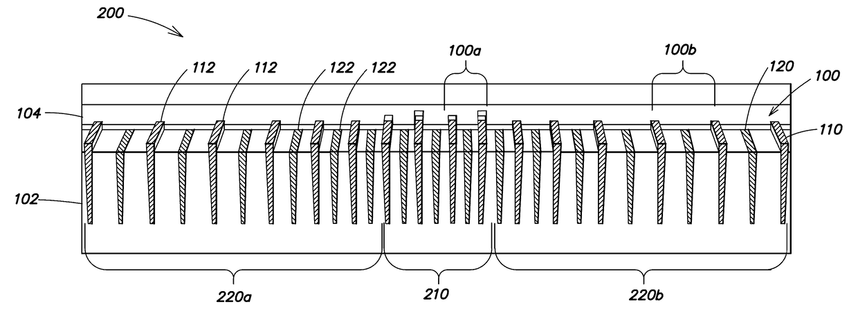
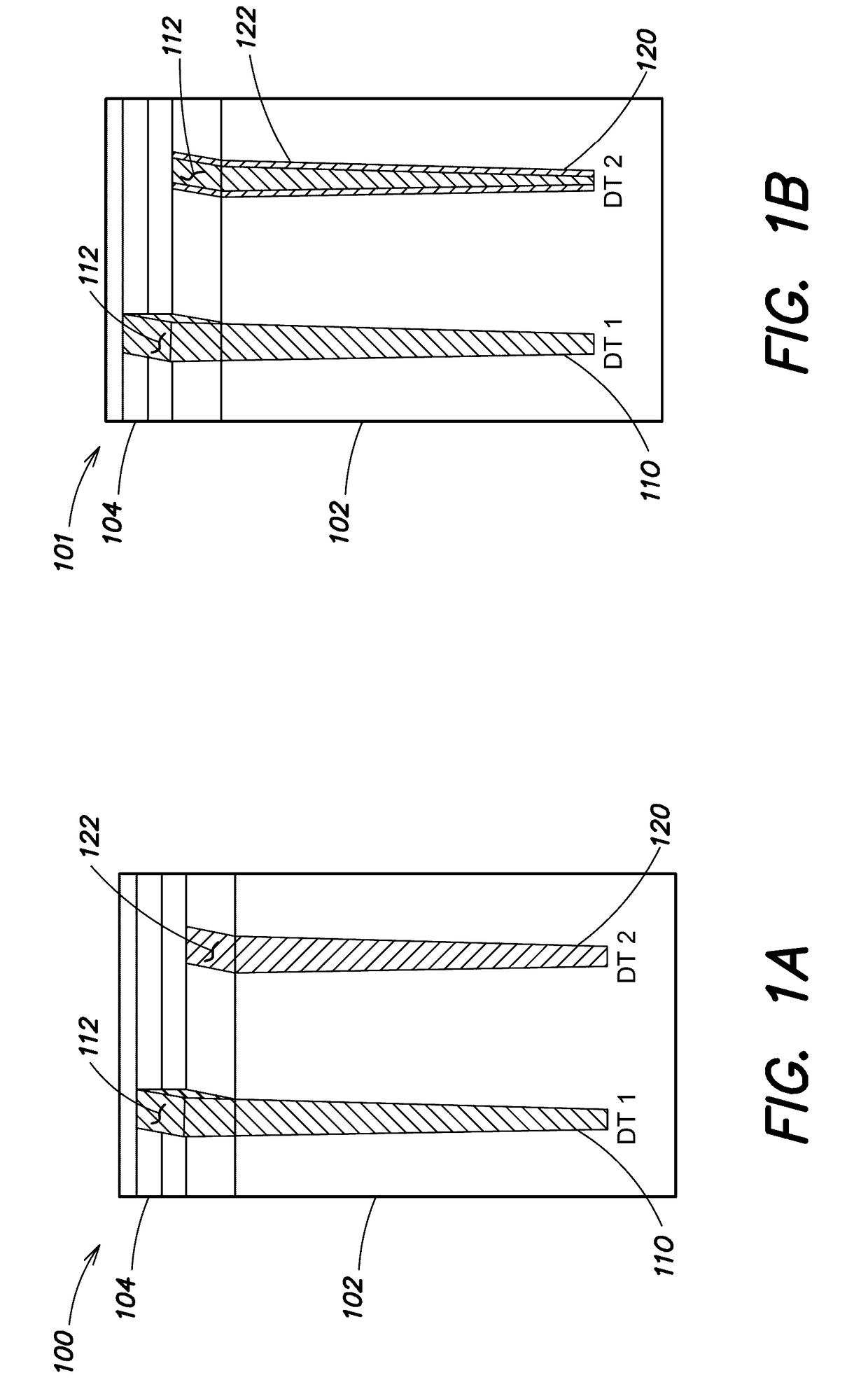
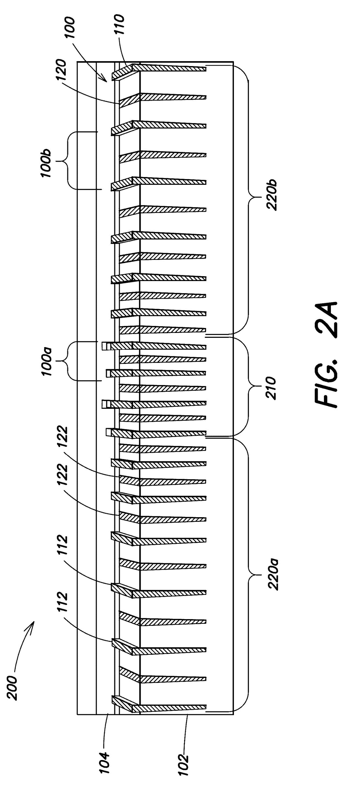
[0046]A dual-trench deep-trench (DTDT) resonator has a unit cell that includes two deep trenches (DTs): a first DT for electrical transduction and a second DT that modulates the mechanical bandgap size, which in turn determines the DTDT resonator's resonance frequency and the band over which the DTDT resonator transmits and / or reflects acoustic waves. The second DT may have a size and filling selected to define a mechanical bandgap that is small enough to provide low reflectivity and trap acoustic waves, yet large enough not to be affected by process variations or to cause cavity matching problems. For example, by partially filling the second DT of a DT unit cell with oxide, the mechanical bandgap can be tuned to just the right size to support a high Q mode, and at the same time be large enough not to be eliminated due to process variations. The use of two DTs per unit cell enables a greater range of mechanical bandgap sizes without breaking the translational symmetry that leads to ...


PUM


Abstract

A deep trench (DT) MEMS resonator includes a periodic array of unit cells, each of which includes a single DT formed in a semiconductor substrate and filled with a material whose acoustic impedance is different than that of the substrate. The filled DT is used as both an electrical capacitor and a mechanical structure at the same time, making it an elegant design that reduces footprint and fabrication complexity. Adding a second DT to each unit cell in a DT MEMS resonator forms a dual-trench DT (DTDT) MEMS resonator. In a DTDT unit cell, the first DT is filled with a conductor to sense, conduct, and / or generate an acoustic wave. The second DT in the DTDT unit cell is filled with an insulator. The width, filling, etc. of the second DT in the DTDT unit cell can be selected to tune the acoustic passband of the DTDT unit cell.

Description

CROSS-REFERENCE TO RELATED PATENT APPLICATION[0001]This application is a bypass continuation of International Application No. PCT / US2016 / 012794, filed on Jan. 11, 2016, and entitled “Dual Trench Deep Trench-Based Unreleased MEMS Resonators,” which in turn claims priority, under 35 U.S.C. §119(e), from U.S. Application No. 62 / 150,399, filed Apr. 21, 2015, and entitled “Dual Trench Deep Trench based Unreleased Coupled MEMS Resonators.” Each of these applications is hereby incorporated herein by reference in its entirety.GOVERNMENT SUPPORT[0002]This invention was made with Government support under Grant No. N66001-13-1-4022 awarded by the Space and Naval Warfare Systems Center and under Grant No. ECCS-1150493 awarded by the National Science Foundation. The Government has certain rights in the invention.BACKGROUND[0003]The demand for small, high performance wireless communication devices has pushed research interests towards the design and development of low power, small footprint, and ...

Claims


Application Information

Patent Timeline
IPC IPC(8): H03H9/17H03H3/02H01G4/06
CPCH03H9/17H01G4/06H03H2003/027H03H2009/155H03H3/02H03H9/2405
Inventor WANG, WENTAOWEINSTEIN, DANA
Owner MASSACHUSETTS INST OF TECH
Why Eureka
Try Eureka