
Large energy density batteries

a large energy density, battery technology, applied in the direction of cell components, cell component details, electrochemical generators, etc., can solve the problems of unsafe li metal anodes in li—s batteries, unreliable, and high cos

Active Publication Date: 2017-06-15
TEXAS A&M UNIVERSITY
View PDF6 Cites 15 Cited by
  • Summary
  • Abstract
  • Description
  • Claims
  • Application Information

AI Technical Summary

Benefits of technology

This patent describes a device that uses a special design to improve the performance of batteries that use lithium and sulfur. The device includes a microporous anode made of lithiated silicon, and a mesoporous cathode made of sulfur and carbon. The cathode is housed in a reservoir of liquid catholyte. The device can be used to create a semi-liquid lithium-sulfur battery. The method of synthesizing the cathode and anode is also provided. The technical effects of the invention are improved energy density and longer life of lithium-sulfur batteries.

Problems solved by technology

However, cobalt based cathodes are too expensive to be used for large-scale systems such as electric vehicles and renewable energy harvesting systems.
For instance, a single charge of an electric vehicle is unable to sustain current standard driving distance per charge (˜500 km).
On the contrary, the Li metal anode in Li—S batteries is unsafe, unreliable, and expensive.
Li—S batteries also have relatively fast capacity fading during cycling due to polysulfide shuttle mechanisms, making the lifetime of Li—S batteries shorter than the demand of current energy storage devices.
The repeated shuttle process during the cycling of the cell considerably reduces the active mass in the cathode, leading to low columbic efficiency and fast capacity fading due to the polysulfide shuttle phenomenon.
Additionally, it has been noted that the Li metal in Li—S batteries causes a safety hazard and short life time due to the formation of lithium dendrite and an internal short-circuit, which may result in thermal runaway.
Even after decades of research efforts, this problem has not been resolved sufficiently to see commercially available rechargeable batteries with a Li metal anode.

Method used


Image

  • Large energy density batteries
  • Large energy density batteries
  • Large energy density batteries

Examples


working examples

[0051]Synthesis of carbon-coated mesoporous Si (C-mSi). Mesoporous Si was synthesized by a magnesiothermic method. Mesoporous SiO2, SBA-15 was prepared, and then mixed and ground with Mg powder (molar ratio of Mg:Si=2:1) in a mortar. The mixture was then sealed in a ¼″ Swagelok coupling and transferred to a tube furnace in Ar (100 sccm). The temperature was ramped up to 650° C. at a rate of 5° C. / min, and kept constant for 2 h. The obtained powders were washed with 2-M HCl overnight and then 5-wt % HF for 10 min. After washing the powder with ample deionized water, the obtained bright-brown Si powders were vacuum-dried at 60° C. for 6 h. To obtain a carbon coating, the Si powders in a crucible were transferred into a tube furnace, and temperature was ramped up to 800° C. in 30 min in a flow of 100-sccm Ar, and then 20-sccm C2H2 was added to the Ar flow for 15 min. By measuring the weight of the powders before and after the carbon coating, carbon contents in the power was estimated t...


PUM

PropertyMeasurementUnit
distanceaaaaaaaaaa
voltageaaaaaaaaaa
thickaaaaaaaaaa

Abstract

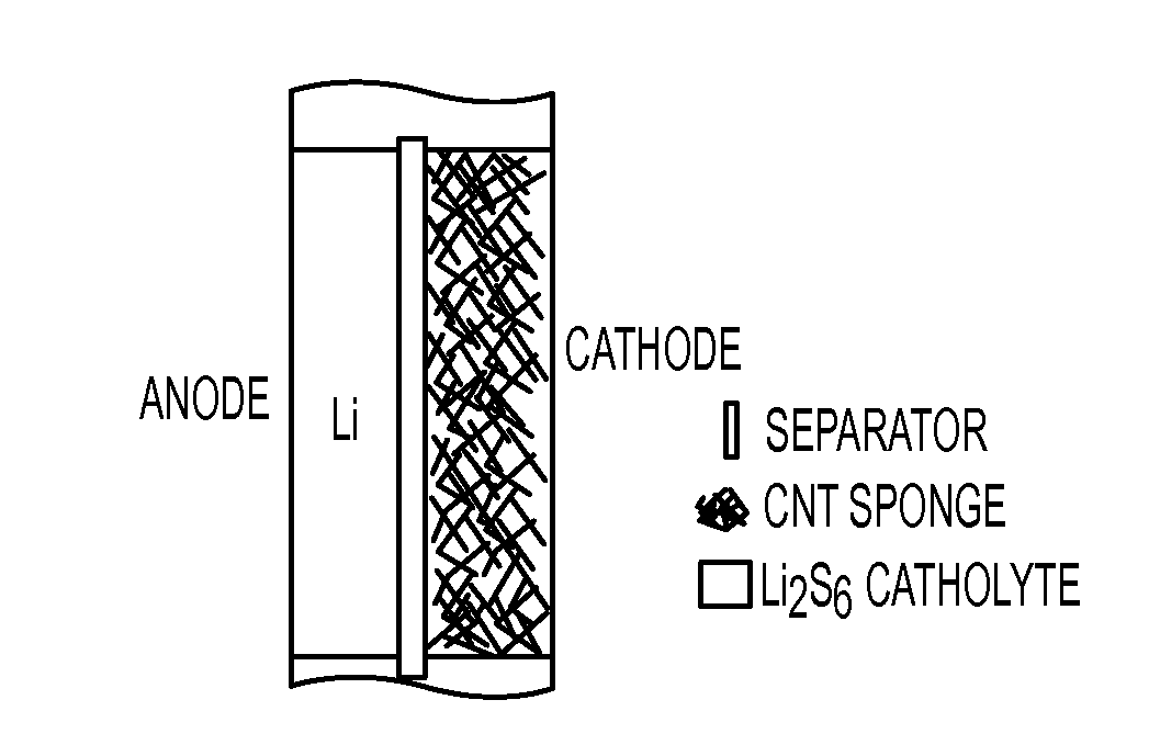
Embodiments of the claimed invention are directed to a device, comprising: an anode that includes a lithiated silicon-based material and a sulfur-based cathode, wherein the anode and the cathode are designed to have mesoporous structures. In certain embodiments, the sulfur-based cathode is a mesoporous carbon structure comprising sulfur within the mesopores. A further embodiment of the invention is directed to a device comprising a semi-liquid lithium-sulfur battery comprising a lithium anode and a sulfur cathode. In certain embodiments, the sulfur cathode comprises a liquid catholyte, which is housed within a reservoir that is a carbon nanotube sponge. An additional embodiment of the invention is directed to a method for producing a lithiated silicon anode and a sulfur-based cathode.

Description

CROSS-REFERENCE TO RELATED APPLICATIONS[0001]This application claims the benefit of U.S. Provisional Patent Application Ser. No. 62 / 025,000, filed on Jul. 15, 2014, which is incorporated herein by reference in its entirety.STATEMENT REGARDING FEDERALLY SPONSORED RESEARCH AND DEVELOPMENT[0002]This invention was made with government support under Grant No. CMMI 1030958 awarded by the National Science Foundation and Grant No. 2011-0001645 awarded by the Pioneer Research Center Program through the National Research Foundation of Korea. The government has certain rights in the invention.BACKGROUND OF THE INVENTION[0003]The most widely used Li-ion batteries are LiCoO2 based cells, which possess good energy density and life cycles. However, cobalt based cathodes are too expensive to be used for large-scale systems such as electric vehicles and renewable energy harvesting systems. Higher energy density, better reliability, and improved safety are also necessary for widespread use of Li-ion ...

Claims


Application Information

Patent Timeline
Patent Type & Authority Applications(United States)
IPC IPC(8): H01M10/052H01M4/38H01M4/66H01M2/16H01M10/0566H01M4/134H01M4/133
CPCH01M10/052H01M4/134H01M4/38H01M2004/021H01M2/1613H01M10/0566H01M4/663H01M4/133H01M4/1393Y02E60/10H01M50/44
Inventor YU, CHOONGHOPU, XIONG
Owner TEXAS A&M UNIVERSITY
Learn More