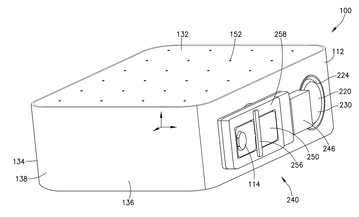
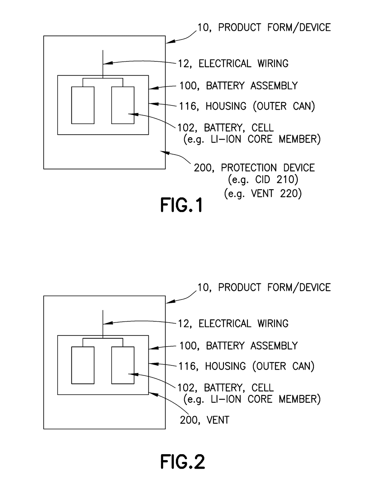
Energy storage device and related methods
a technology of energy storage and energy storage components, applied in the direction of vent arrangements, cell components, batteries, etc., can solve the problems of releasing a significant amount of thermal energy, energy storage assemblies, battery suffers, etc., and achieves sufficient stiffness and strength, the effect of high rigidity and strength
- Summary
- Abstract
- Description
- Claims
- Application Information
AI Technical Summary
Benefits of technology
Problems solved by technology
Method used
Image
Examples
##ic example 1
PROPHETIC EXAMPLE 1
Method of Making Housing
[0259]In this configuration, the housing / enclosure body is formed via a forming operation (e.g. drawing and ironing) in order to provide a base with a perimetrical sidewall extending upward and surrounding the base, thus defining an inner void. The inner void is configured / sufficiently sized to accommodate a plurality of energy storage devices.
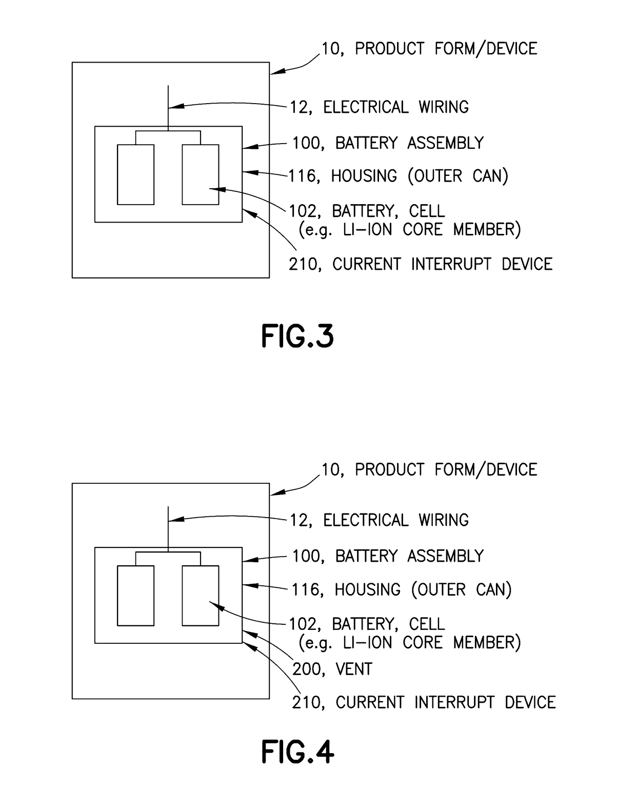
[0260]At a position along the sidewall (e.g. positioned a sufficient distance from the electrode leads, terminal contacts and / or electrical wiring of the energy storage devices) a portion of the housing sidewall is removed to accommodate the attachment of a current interrupt device. The current interrupt device is attached (e.g. welded, fastened, bonded, and / or adhered) to the housing and configured to interrupt electrical contact if the internal atmosphere of the housing reaches / exceeds a predetermined pressure. The current interrupt device is configured onto the sidewall of the housing such that the...
##ic example 2
PROPHETIC EXAMPLE 2
Method of Assembly Li-Ion Core Members (e.g. Jelly Roll)
[0265]In this configuration, the individual energy storage devices are retained in a housing that is sealed via a forming operation (e.g. double seaming). In this instance, the jelly rolls are placed into the housing, electrolyte is inserted into the jelly rolls and a charge / discharge cycle is completed in order to prepare the li-ion core members. Once the li-ion core members are primed (e.g. configured for electrical storage, charge, and discharge operation), the lid of the housing is positioned over the open, upper end of the housing body, overlapping a perimetrical lip (e.g. flange) on the upper end of the housing with a corresponding flange / lip perimetrically located on the lid / cover. Through a forming operation, the corresponding flanges are joined to form a double seal (e.g. having a sealing compound positioned between the layers to assist in achieving a hermetic seal).
##ic example 3
PROPHETIC EXAMPLE 3
Method of Assembly with Wire Fuse
[0266]In this configuration, the individual energy storage devices are each retained in a sleeve, with the plurality of energy storage devices set into a larger housing / enclosure configured to seal (e.g. hermetically seal) around / about the energy storage devices.
[0267]The inner can and ends are manufactured (e.g. via a forming operation, via an extrusion), with inner end having / configured with a central hole for the electrical contact / wiring (e.g. copper lead) to exit the energy storage device. Then, the outer cans (e.g. housing / enclosure), including body and cover (or ends) is manufactured.
[0268]Each energy storage device is loaded into an inner can, and a weld (e.g. ultrasonic weld or laser weld) is positioned adjacent to the bottom of the can (e.g. where the weld is an aluminum contact configured between the energy storage device and the container). The electrical contact / wiring is threaded through the central hole in the top, f...
PUM
 Abstract
Description
Claims
Application Information
 - R&D
- Intellectual Property
- Life Sciences
- Materials
- Tech Scout
- Unparalleled Data Quality
- Higher Quality Content
- 60% Fewer Hallucinations
Browse by: Latest US Patents, China's latest patents, Technical Efficacy Thesaurus, Application Domain, Technology Topic, Popular Technical Reports.
© 2025 PatSnap. All rights reserved.Legal|Privacy policy|Modern Slavery Act Transparency Statement|Sitemap|About US| Contact US: help@patsnap.com


