Method and apparatus for producing powder and method for manufacturing shaped object
a technology of shaped objects and powders, which is applied in the direction of solid-state diffusion coatings, transportation and packaging, coatings, etc., can solve the problems of insufficient nitrogen content in the density of the resulting shaped object is reduced to about 85%, and the resulting shaped object cannot have the desired hardness, etc., to achieve accurate control, increase the penetration speed of nitrogen, and increase the time for plasma generation
- Summary
- Abstract
- Description
- Claims
- Application Information
AI Technical Summary
Benefits of technology
Problems solved by technology
Method used
Image
Examples
example 1
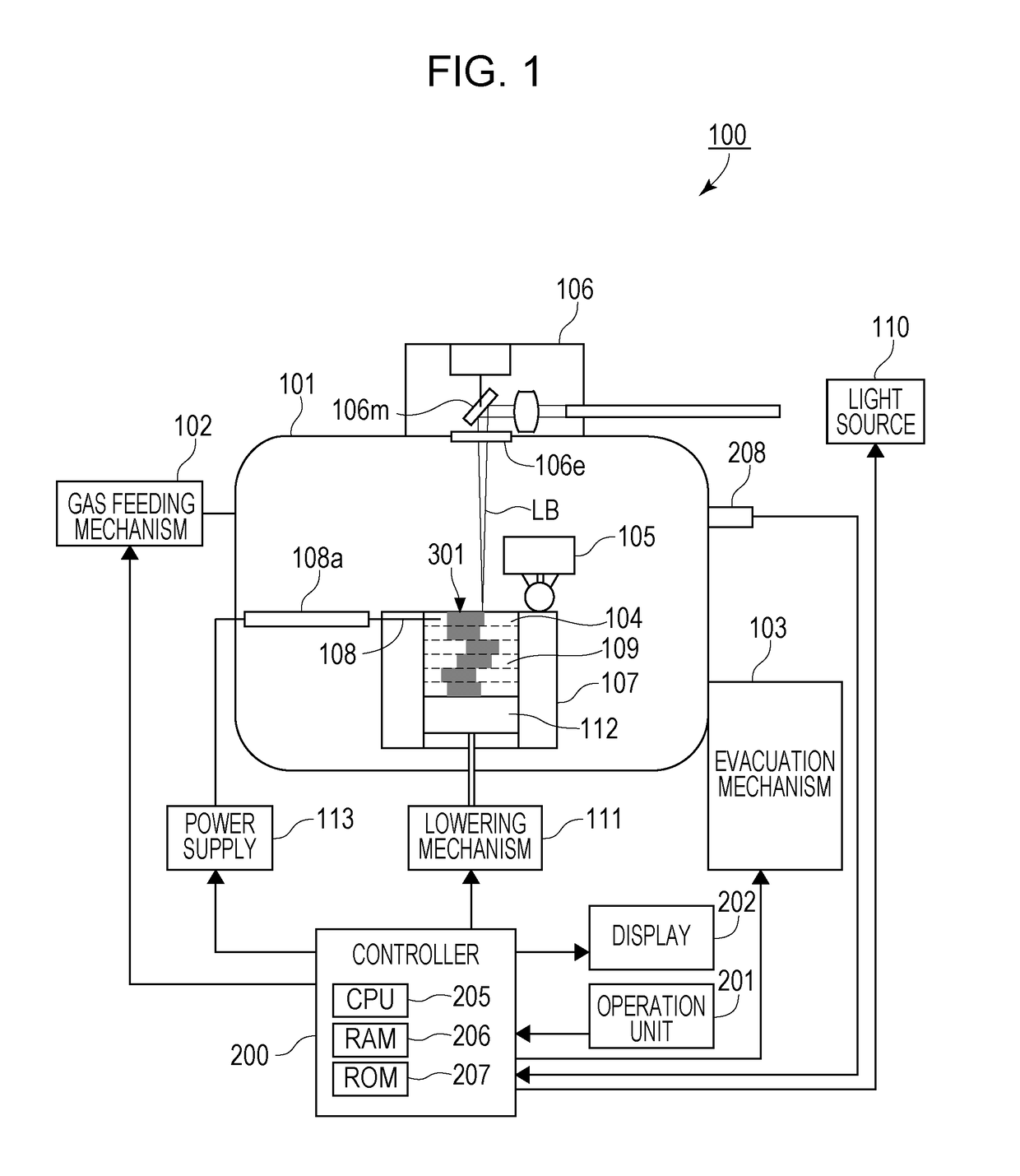
[0046]In Example 1, stainless steel particles were subjected to plasma nitridation and laser beam sintering under the following conditions.
Conditions for Plasma Nitridation
[0047]Pressure in Chamber 101: 13.3 kPa[0048]Gas to be fed: Mixture of nitrogen gas and hydrogen gas in a ratio of 1:1[0049]Raw material powder: stainless steel (SUS 613) particles having a particle size of 7 μm produced by water atomization[0050]Thickness of thin layers 104: 20 μm[0051]Voltage: alternating voltage of 1 kV with a frequency of 100 kHz[0052]Plasma nitridation time: 3 minutes
Conditions for Laser Beam Heating Formation
[0053]Portion to be melted: a square portion of 25 mm by 25 mm of the thin layer 104[0054]Number of layers: 2000[0055]Height of shaped object 301: 40 mm
[0056]The resulting shaped object 301 of Example 1 was analyzed for the nitrogen content by XPS (X-ray photoemission spectroscopy), and the result was 12% (in terms of number of atoms). Also, the density of the shaped object 301 measured ...
example 2
[0057]In Example 2, titanium particles were subjected to plasma nitridation and laser beam heating formation under the following conditions.
Conditions for Plasma Nitridation
[0058]Pressure in Chamber 101: 13.3 kPa[0059]Gas to be fed: Mixture of nitrogen gas and hydrogen gas in a ratio of 1:1[0060]Raw material powder: titanium (Ti) particles having a particle size of 20 μm produced by water atomization[0061]Thickness of thin layers 104: 40 μm[0062]Voltage: alternating voltage of 20 kV with a frequency of 100 kHz[0063]Plasma nitridation time: 10 minutes
Conditions for Laser Beam Heating Formation
[0064]Portion to be melted: a square portion of 25 mm by 25 mm of the thin layer 104[0065]Number of layers: 100[0066]Height of stack: 4 mm
[0067]Since the particle size of the raw material powder used in Example 2 is larger, the plasma nitridation through the surface of the layer is likely to take a longer time than that in Example 1. Accordingly, the thin layer 104 and the stack of the nitrided ...
example 3
[0069]In Example 3, a mixture of tungsten carbide powder and cobalt powder was subjected to plasma nitridation and laser beam heating formation under the following conditions.
Conditions for Plasma Nitridation
[0070]Pressure in Chamber 101: 13.3 kPa[0071]Gas to be fed: Mixture of nitrogen gas and hydrogen gas in a ratio of 1:5[0072]Raw material powder: mixture prepared by adding 5% of cobalt powder having a particle size of 20 μm produced by water atomization to tungsten carbide having a particle size of 5 μm produced by gas atomization[0073]Thickness of thin layers 104: 40 μm[0074]Voltage: alternating voltage of 20 kV with a frequency of 100 kHz[0075]Plasma nitridation time: 10 minutes
Conditions for Laser Beam Heating Formation
[0076]Portion to be melted: a square portion of 25 mm by 25 mm of the thin layer 104[0077]Number of layers: 100[0078]Height of stack: 4 mm
[0079]Since the raw material powder used in Example 3 has a higher melting point, the plasma nitridation through the surfac...
PUM
| Property | Measurement | Unit |
|---|---|---|
| pressure | aaaaa | aaaaa |
| pressure | aaaaa | aaaaa |
| thickness | aaaaa | aaaaa |
Abstract
Description
Claims
Application Information
 - R&D
- Intellectual Property
- Life Sciences
- Materials
- Tech Scout
- Unparalleled Data Quality
- Higher Quality Content
- 60% Fewer Hallucinations
Browse by: Latest US Patents, China's latest patents, Technical Efficacy Thesaurus, Application Domain, Technology Topic, Popular Technical Reports.
© 2025 PatSnap. All rights reserved.Legal|Privacy policy|Modern Slavery Act Transparency Statement|Sitemap|About US| Contact US: help@patsnap.com


