
Method Of Deriving Natural Frequency Of Cutting Tool, Method Of Creating Stability Limit Curve, And Apparatus For Deriving Natural Frequency Of Cutting Tool

Inactive Publication Date: 2017-06-01
DMG MORI SEIKI CO LTD
View PDF7 Cites 5 Cited by
  • Summary
  • Abstract
  • Description
  • Claims
  • Application Information

AI Technical Summary

Benefits of technology

The present disclosure describes a method for machining objects using a cutting tool with a derived natural frequency. The natural frequency of the cutting tool is derived based on the displacement of the tool and the cutting force applied during machining, taking into account the influence of the object being machined. This results in a more accurate natural frequency, without the need for an impact hammer and avoiding artificial variations or complicated data selection processes. In addition, a stability limit curve is created based on the natural frequency, ensuring a better match with the actual machining situation.

Problems solved by technology

However, in the conventional method that uses an impact hammer to derive a natural frequency of a cutting tool, artificial variation is likely to occur because the striking using the impact hammer is performed by a human.
Therefore, the conventional method has a problem that it is difficult to obtain an accurate natural frequency of the cutting tool and a problem that technical skills are required in the striking per se in order to obtain appropriate data.
Further, as for a hammer tip attached to the striking portion of the impact hammer, a period of a vibration frequency to be measured (the reciprocal of the frequency) has to be calculated and a hammer tip has to be selected through trial and error so that contact time of the hammer is within a range of about 0.3 to one times the period; therefore, there is also a problem that the selecting operation is very cumbersome.

Method used


Image

  • Method Of Deriving Natural Frequency Of Cutting Tool, Method Of Creating Stability Limit Curve, And Apparatus For Deriving Natural Frequency Of Cutting Tool
  • Method Of Deriving Natural Frequency Of Cutting Tool, Method Of Creating Stability Limit Curve, And Apparatus For Deriving Natural Frequency Of Cutting Tool
  • Method Of Deriving Natural Frequency Of Cutting Tool, Method Of Creating Stability Limit Curve, And Apparatus For Deriving Natural Frequency Of Cutting Tool

Examples


Embodiment Construction

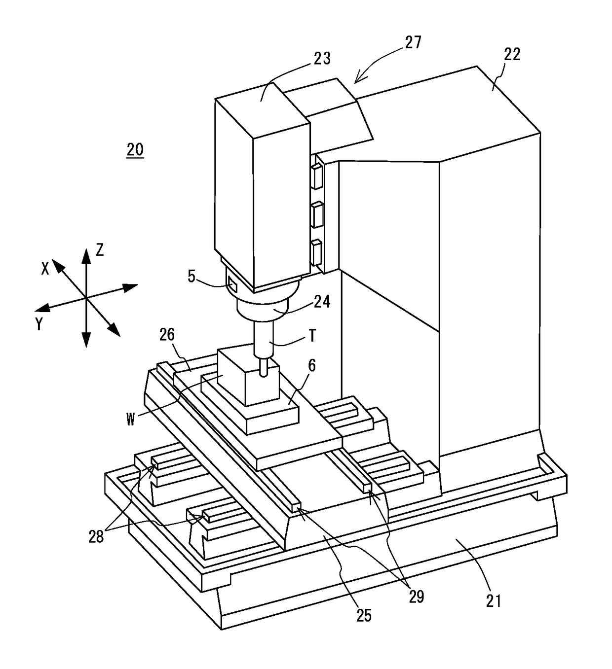
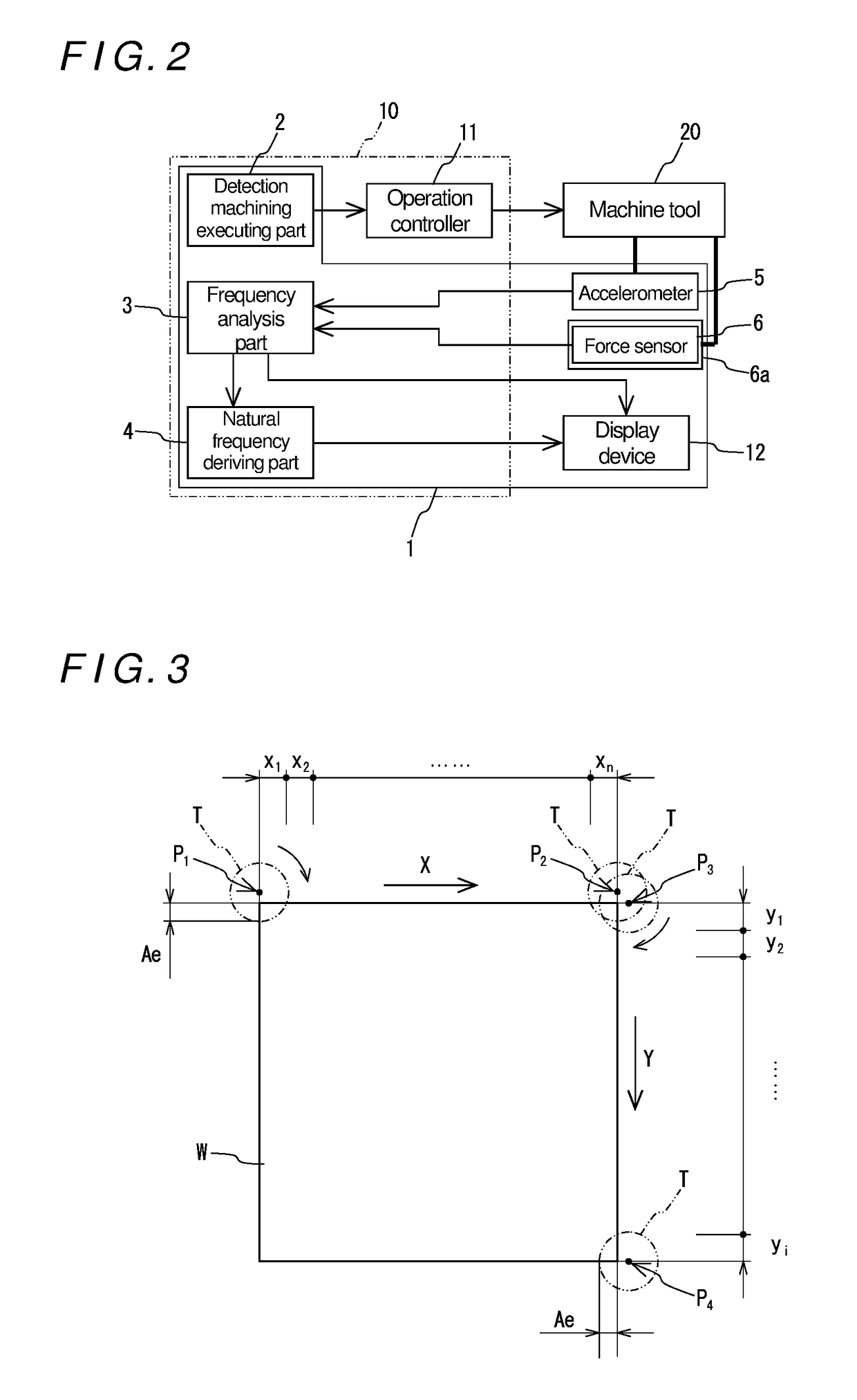
[0081]Hereinafter, a specific embodiment of the present disclosure will be described with reference to the drawings. FIG. 1 is a perspective view of a machine tool used in this embodiment and FIG. 2 is a block diagram showing a natural frequency deriving apparatus and other elements according to this embodiment.

Schematic Configuration of Machine Tool

[0082]First of all, a machine tool 20 is schematically described. This machine tool 20 includes a bed 21, a column 22 erected on the bed 21, a spindle head 23 provided on a front surface (machining area side surface) of the column 22 to be movable in a direction of the Z axis indicated by arrow, a spindle 24 held by the spindle head 23 to be rotatable about an axis thereof, a saddle 25 provided on the bed 21 below the spindle head 23 to be movable in a direction of the Y axis indicated by arrow, a table 26 disposed on the saddle 25 to be movable in a direction of the X axis indicated by arrow, an X-axis feed mechanism 29 for moving the t...


PUM


Abstract

An apparatus includes a machining executing part causing a machine tool to execute an operation of, while changing a spindle rotation speed of the machine tool in a stepwise manner, machining a workpiece by a predetermined distance or for a predetermined period of time at each spindle rotation speed, a displacement detector detecting a position displacement of a tool during the machining, a cutting force detector detecting a cutting force applied to the tool, a frequency analysis part performing frequency analysis on displacement data and cutting force data for each rotation speed to calculate a displacement spectrum and a cutting force spectrum, and a natural frequency deriving part calculating a compliance spectrum for each spindle rotation speed by deriving the displacement spectrum by the cutting force spectrum, calculating an integrated compliance spectrum by superimposing the compliance spectra, and deriving, as a natural frequency, a frequency showing the largest compliance value.

Description

BACKGROUND[0001]Field of the Disclosure[0002]The present disclosure relates to a method of deriving a natural frequency of a cutting tool used in machining an object to be machined (workpiece) with a machine tool and a method of creating a stability limit curve concerning regenerative chatter of the cutting tool, as well as an apparatus for deriving the natural frequency of the cutting tool.[0003]Background of the Disclosure[0004]In machining a workpiece with a machine tool, it has been well known that machining accuracy (in particular, surface accuracy) is impaired by chatter vibration. Such chatter vibration is roughly classified into forced chatter vibration and self-exited chatter vibration, and forced chatter vibration is considered to occur when an excessive external force is applied or when a frequency of an external force is synchronized with a resonance frequency of a vibrating system. On the other hand, self-exited chatter vibration includes regeneration type chatter vibra...

Claims


Application Information

Patent Timeline
IPC IPC(8): G01N29/44G01N29/04B23Q17/09
CPCG01N29/449G01N2291/014G01N29/045B23Q17/0971B23Q17/0952B23Q17/22G06F30/17B23Q11/0039G01N29/14G01N29/46G01M1/30B23Q11/0032B23Q17/0976B23Q17/12B23Q2717/00G05B19/401
Inventor KAWAI, KENGOONO, KATSUHIKONISHIKAWA, SHIZUO
Owner DMG MORI SEIKI CO LTD
Learn More