Switching power supply apparatus

a power supply apparatus and power supply technology, applied in the direction of power conversion systems, dc-dc conversion, instruments, etc., can solve the problems of increasing the size of the apparatus, the inability to directly measure a voltage across the switching element, and the measurement terminal for externally measuring a voltage is not usually provided, so as to reduce or prevent the output of an overvoltage, reduce or prevent the effect of buffer influen

Active Publication Date: 2017-05-25
MURATA MFG CO LTD
View PDF0 Cites 4 Cited by
  • Summary
  • Abstract
  • Description
  • Claims
  • Application Information

AI Technical Summary

Benefits of technology

The patent text describes a configuration for measuring voltages in a switching power supply apparatus. The configuration includes a converter and a semiconductor device. The text explains that errors can occur when measuring the voltages at both ends of the semiconductor device, but the errors are not significantly different. The text suggests that by calculating the measurement values in the same way, the influence of errors can be significantly reduced or prevented. The text also mentions that by measuring the voltage at the input or output of the converter, the measurement value of the first semiconductor device can be corrected, resulting in a more accurate output voltage. This allows for a smaller-sized switching power supply apparatus with high accuracy.

Problems solved by technology

However, a measurement terminal for externally measuring a voltage is not usually provided in the middle of a circuit.
It is therefore not possible to directly measure a voltage across a switching element and correct a voltage value as disclosed in Japanese Unexamined Patent Application Publication No. 2013-78203.
This leads to an increase in the size of an apparatus.

Method used


Image

  • Switching power supply apparatus
  • Switching power supply apparatus
  • Switching power supply apparatus

Examples


first preferred embodiment

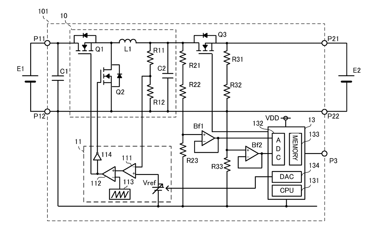
[0041]FIG. 1 is a circuit diagram of a switching power supply apparatus 101 according to a first preferred embodiment of the present invention.

[0042]A direct-current power supply E1 is electrically connected to voltage input portions P11 and P12 of the switching power supply apparatus 101. A battery E2 is electrically connected to voltage output portions P21 and P22 of the switching power supply apparatus 101. The switching power supply apparatus 101 steps down a direct-current voltage supplied from the direct-current power supply E1 and outputs a resultant voltage to the battery E2. The battery E2 is charged with the voltage.

[0043]A synchronous-rectification-type step-down converter 10 is electrically connected to the voltage input portions P11 and P12 via an input capacitor C1. The step-down converter 10 includes switching elements Q1 and Q2, an inductor L1, and a capacitor C2. The switching elements Q1 and Q2 are n-type MOS-FETs, and switching of the switching elements Q1 and Q2 ...

second preferred embodiment

[0068]FIG. 4 is a circuit diagram of a switching power supply apparatus 102 according to a second preferred embodiment of the present invention.

[0069]In the second preferred embodiment, the switching power supply apparatus 102 includes a diode D1 instead of the switching element Q3 shown in FIG. 1. The diode D1 corresponds to the first semiconductor device. An anode of the diode D1 is electrically connected to the step-down converter 10, and a cathode of the diode D1 is electrically connected to the voltage output portion P21. Except for the diode D1, the switching power supply apparatus 102 includes the same or similar circuit configuration as in the first preferred embodiment. The diode D1 significantly reduces or prevents the backflow of a current from the battery E2. In this case, switching control of the diode D1 does not need to be performed.

third preferred embodiment

[0070]FIG. 5 is a circuit diagram of a switching power supply apparatus 103 according to a third preferred embodiment of the present invention.

[0071]Similar to the first preferred embodiment, the switching power supply apparatus 103 of the third preferred embodiment includes the step-down converter 10 and the switching element Q3 electrically connected to an output side of the step-down converter 10. In the third preferred embodiment, the connection direction of the switching element Q3 is opposite to that of the first preferred embodiment. More specifically, the source of the switching element Q3 is electrically connected to the step-down converter 10, and the drain of the switching element Q3 is electrically connected to the voltage output portion P21.

[0072]The switching power supply apparatus 103 further includes a current detection circuit 14 electrically connected between the switching element Q3 and the voltage output portion P21. The current detection circuit 14 is included t...


PUM


Abstract

A switching power supply apparatus includes a step-down converter that steps down an input current by turning on / off switching elements, a switching element electrically connected between the step-down converter and voltage outputs, and a microcontroller. An input-side resistor voltage dividing circuit and an output-side resistor voltage dividing circuit including elements with the same or similar specifications are electrically connected to the input and output of the switching element, respectively. The microcontroller stores coefficients of an expression which have been externally calculated according to a voltage detected by the output-side resistor voltage dividing circuit and a voltage detected at the voltage output portions. The microcontroller corrects a measurement value of an intermediate bus voltage detected by the input-side resistor voltage dividing circuit according to an expression and the stored coefficients.

Description

CROSS REFERENCE TO RELATED APPLICATIONS[0001]This application claims the benefit of priority to Japanese Patent Application No. 2014-159118 filed on Aug. 5, 2014 and is a Continuation application of PCT Application No. PCT / JP2015 / 065183 filed on May 27, 2015. The entire contents of each application are hereby incorporated herein by reference.BACKGROUND OF THE INVENTION[0002]1. Field of the Invention[0003]The present invention relates to a switching power supply apparatus including a converter.[0004]2. Description of the Related Art[0005]In a switching power supply including a converter, the voltage and current of the converter are measured for the detection of an abnormality or an operating state. An error or deviation in an output voltage caused by variations in resistance of wiring and a reference voltage is stored in a storage device at the time of factory shipment for the purpose of correcting such an error or deviation.[0006]For example, Japanese Unexamined Patent Application P...

Claims


Application Information

Patent Timeline
Patent Type & Authority Applications(United States)
IPC IPC(8): H02M3/156
CPCH02M3/156H02M3/155H02M1/0025
Inventor UNO, YOSHIYUKI
Owner MURATA MFG CO LTD
Why Eureka
Try Eureka