
Interventional MRI Compatible Medical Device, System, and Method

Inactive Publication Date: 2017-05-25
GEORGIA TECH RES CORP +1
View PDF4 Cites 5 Cited by
  • Summary
  • Abstract
  • Description
  • Claims
  • Application Information

AI Technical Summary

Benefits of technology

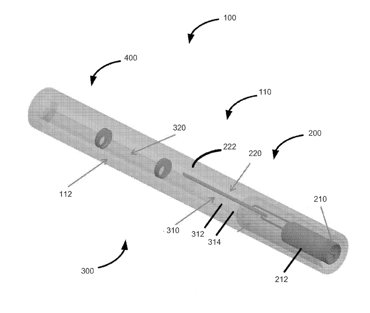
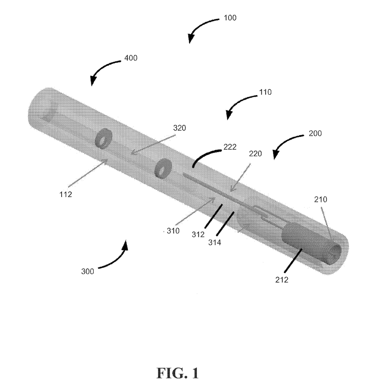
The present invention provides a MRI compatible medical device that includes an electro-mechanical conversion assembly, a mechanical-optical conversion assembly, and a signal transmitter / detector assembly. This combination of three assemblies allows for the detection of an active receiver using an RF heating free, dielectric transmission line resulting in a safe and visible catheter. The invention offers the possibility of combined temperature measurement and optical detuning capability which is a significant advance in the field of interventional MRI. The integration of an acousto-optical detector to an MRI catheter and its successful demonstration as an active receiver with a non-conducting transmission line is a significant step in achieving the goal of more effective, more efficient, safer, novel, and radiation-free interventional procedures. This patent text also paves the way to safer and cost-effective devices that can detect and transmit local temperature and MRI signals over the same optical fiber.

Problems solved by technology

Interventional cardiovascular magnetic resonance imaging (MRI) has the potential as an ionizing radiation-free alternative to conventional X-ray guided catheterization, but its use has so far been limited in clinical settings because of lack of safe and conspicuous catheter devices.
Engineering safe and conspicuous MRI catheters is especially challenging because of the combination of electrical and mechanical requirements and profile constraints discussed above.
An important problem for interventional MRI device safety is the radio frequency (RF) induced heating over incorporated long conductive materials.
The resonant length of the conductor is a main contributor to heating, but it is a complex problem since partial guide wire insertion from air into the body creates complex resonance patterns during clinical use as the operator moves the device.
While detuning circuitry can mitigate inductive coupling between the guide wire and RF transmitter, capacitive coupling is more difficult to suppress.
A second problem is visibility.
Passively-visualized devices have poor contrast dependent on the device orientation relative to the main magnetic field and often create image artifacts.
However none of these techniques can offer active device design that can have clinically acceptable mechanical performance.
Each of the three fields associated with MRI present safety risks to patients when a medical device is in close proximity to or in contact either externally or internally with patient tissue.
One important safety risk is the heating that can result from an interaction between the RF field of the MRI scanner and the medical device (RF-induced heating), especially medical devices which have elongated conductive structures with tissue contacting electrodes, such as electrode wires in pacemaker and implantable cardioverter defibrillator (ICD) leads, guidewires, and catheters.

Method used


Image

  • Interventional MRI Compatible Medical Device, System, and Method
  • Interventional MRI Compatible Medical Device, System, and Method
  • Interventional MRI Compatible Medical Device, System, and Method

Examples


Embodiment Construction

[0045]To facilitate an understanding of the principles and features of the various embodiments of the invention, various illustrative embodiments are explained below. Although exemplary embodiments of the invention are explained in detail, it is to be understood that other embodiments are contemplated. Accordingly, it is not intended that the invention is limited in its scope to the details of construction and arrangement of components set forth in the following description or illustrated in the drawings. The invention is capable of other embodiments and of being practiced or carried out in various ways. Also, in describing the exemplary embodiments, specific terminology will be resorted to for the sake of clarity.

[0046]It must also be noted that, as used in the specification and the appended claims, the singular forms “a,”“an” and “the” include plural references unless the context clearly dictates otherwise. For example, reference to a component is intended also to include composit...


PUM


Abstract

An active catheter design incorporating a distal loop coil that is electrically connected to an ultrasonic transducer having a comparable profile. The ultrasonic transducer induces ultrasonic waves at the Larmor frequency at the distal end of a dielectric optical fiber that runs along the active catheter shaft. The optical fiber serves as the transmission line instead of a convention conductor, eliminating the RF induced heating. The dynamic strain generated by the ultrasonic transducer can be measured using optical interferometry by coupling a laser at the proximal end of the optical fiber using the acousto-optical effect. A fiber embedded Bragg reflector grating, for example, can be used for this purpose. The device can also be used for simultaneous temperature measurements among other parameters.

Description

CROSS-REFERENCE TO RELATED APPLICATIONS[0001]This application claims the benefit of U.S. Provisional Application No. 61 / 977,700 filed 10 Apr. 2014 the entire contents and substance of which is hereby incorporated by reference.BACKGROUND OF THE INVENTION[0002]1. Field of the Invention[0003]The present invention relates generally to MRI compatible devices, systems and methods, and more specifically to a clinical-grade active catheter device that does not need long conductor transmission lines for active device visualization under MRI.[0004]2. Description of Related Art[0005]Interventional cardiovascular magnetic resonance imaging (MRI) has the potential as an ionizing radiation-free alternative to conventional X-ray guided catheterization, but its use has so far been limited in clinical settings because of lack of safe and conspicuous catheter devices. Engineering safe and conspicuous MRI catheters is especially challenging because of the combination of electrical and mechanical requi...

Claims


Application Information

Patent Timeline
IPC IPC(8): A61B5/06G01R33/28G01R33/36A61B5/055
CPCA61B5/061G01R33/3692G01R33/285A61B5/055A61B8/12A61B5/6852A61B5/0097A61B5/01A61B2562/0271A61B8/445A61B5/065A61B5/06A61B5/062
Inventor DEGERTEKIN, FAHRETTIN LEVENTKOCATURK, OZGUR
Owner GEORGIA TECH RES CORP
Learn More