Sound generator for mounting on a vehicle to manipulate vehicle noise
a sound generator and vehicle technology, applied in the direction of electrical transducers, instruments, electrical equipment, etc., can solve the problems of reducing the overall efficiency of the vehicle, not being able to achieve such a distinctive noise emission in a natural way, and being difficult to manufacture cost-effectively. , to achieve the effect of robust mounting and operation, and cost-effective manufactur
- Summary
- Abstract
- Description
- Claims
- Application Information
AI Technical Summary
Benefits of technology
Problems solved by technology
Method used
Image
Examples
first embodiment
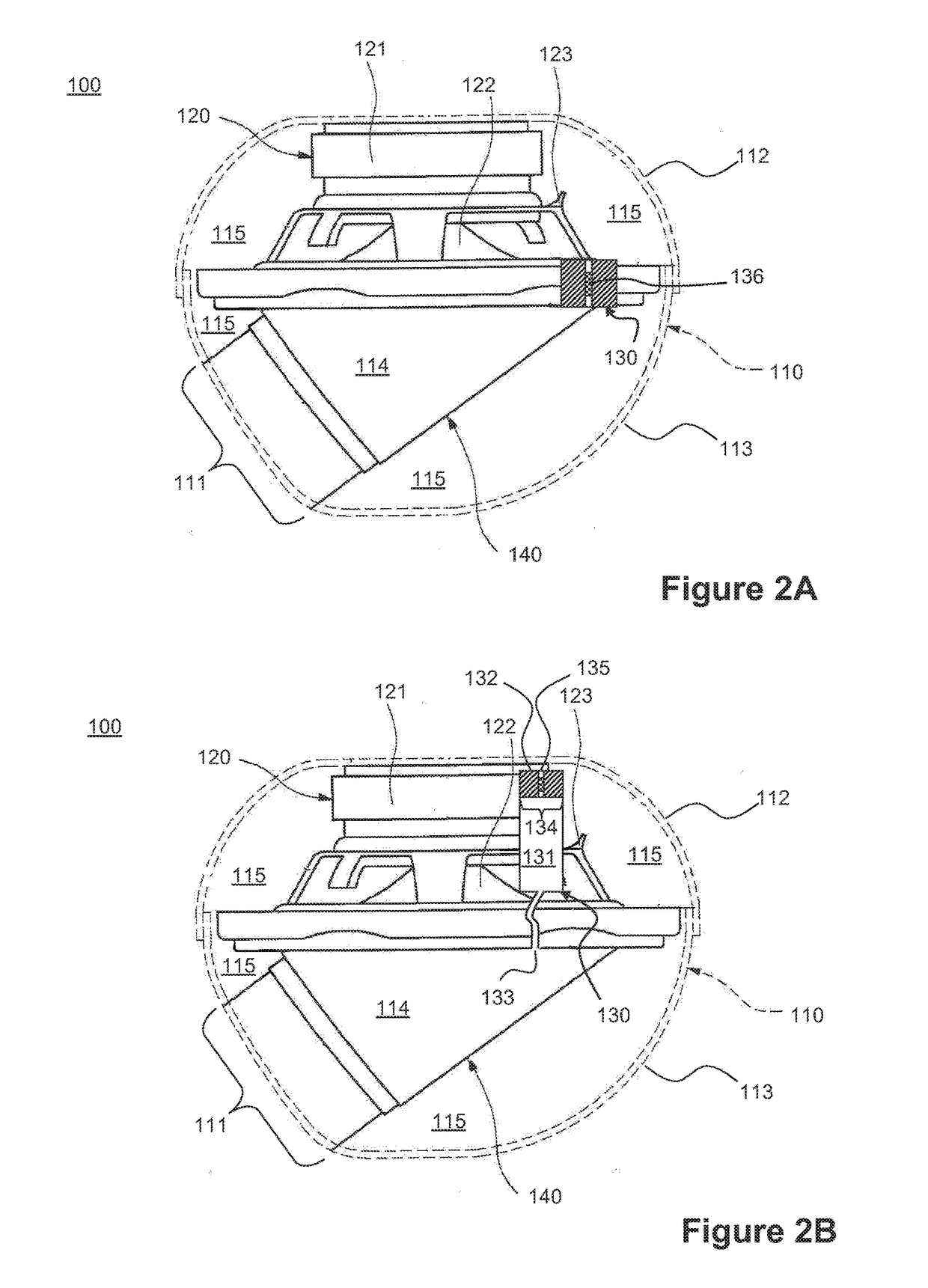
[0058]Referring to the drawings, a sound generator according to the invention is described referencing FIG. 2A. FIG. 2A thereby shows a cross-section through the sound generator 100 in a schematic view.
[0059]The sound generator 100 shown in FIG. 2A comprises a casing 110 formed from a lower shell 113 and an upper shell 112 coupled to the lower shell 113 in an airtight manner. Both, the lower shell 113 and the upper shell 112 are made from a stainless steel panel.
[0060]The lower shell 113 of the casing 110 includes a casing aperture 111 and receives a bell mouth 140 also made from a stainless steel panel. In the region of the casing aperture 111 an outside of the bell mouth 140 is coupled to the lower shell 113 of the casing 110 in an airtight manner. An opening of the bell mouth 140 is aligned with the casing aperture 111 of the sound generator 100. The bell mouth 140 of the embodiment illustrated is configured for being coupled to an exhaust system as shown in FIG. 1A for a prior a...
fourth embodiment
[0073]Further, no bell mouth is present inside the casing 110 of the sound generator 100 and the casing 110 is also not made in two parts by an upper shell and a lower shell. The casing is rather made cup-shaped from polyvinyl chloride and is sealed by the loudspeaker basket 123 of the voice coil loudspeaker 120 supported by the casing 110. This results in the voice coil loudspeaker 120 separating the rear volume 115 enclosed by the loudspeaker 120 and the casing 110 from the air 114′ at the other side of the voice coil loudspeaker 120. Hence, the rear volume 115 communicates also in this case only through the pressure compensation valve 130 with air 114′ on the other side of the voice coil loudspeaker 120.
[0074]FIG. 3A illustrates a first operating condition, where only air 114′ surrounds the sound generator 100. A pressure compensation between the rear volume 115 and the air 114′ on the other side of the voice coil loudspeaker 120 through the pressure compensation valve 130 is po...
PUM
 Abstract
Description
Claims
Application Information
 - R&D
- Intellectual Property
- Life Sciences
- Materials
- Tech Scout
- Unparalleled Data Quality
- Higher Quality Content
- 60% Fewer Hallucinations
Browse by: Latest US Patents, China's latest patents, Technical Efficacy Thesaurus, Application Domain, Technology Topic, Popular Technical Reports.
© 2025 PatSnap. All rights reserved.Legal|Privacy policy|Modern Slavery Act Transparency Statement|Sitemap|About US| Contact US: help@patsnap.com


