
Dc/dc converter and electrical storage system

a technology of dc/dc converter and electrical storage system, which is applied in the direction of process and machine control, battery/fuel cell control arrangement, instruments, etc., can solve the problem of not being able to perform step-up operation at a transformation ratio larger than the set transformation ratio, and achieve the effect of increasing the voltage value of the first coil and the voltage value of the second coil

Active Publication Date: 2017-04-20
TOYOTA JIDOSHA KK
View PDF2 Cites 10 Cited by
  • Summary
  • Abstract
  • Description
  • Claims
  • Application Information

AI Technical Summary

Benefits of technology

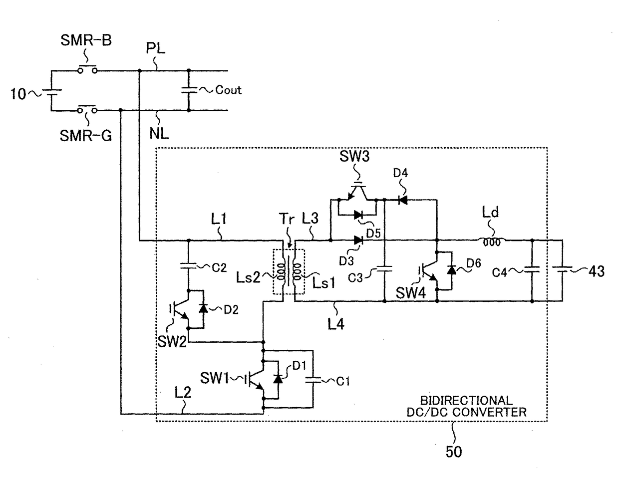
The DC / DC converter described in the patent allows for both step-up and step-down operations using a single transformer. This is achieved by configuring the transformer's transformation ratio for each operation. The transformation ratio determines the ratio of input to output voltage in the converter. In the step-up operation, a reactor is used to store magnetic energy in the transformer, which is then released to increase the voltage value of a low-voltage battery. The converter forms an LC circuit using the transformer and a capacitor to pass exciting current and increase the voltage value of the transformer. The higher voltage value of the transformer is used to charge a smoothing capacitor, which helps to reduce inrush current and stabilize the voltage. Overall, the DC / DC converter allows for efficient voltage conversion and smoother integration of high-voltage and low-voltage batteries.

Problems solved by technology

As described above, if the transformation ratio of the transformer is set in consideration of step-down operation, it is not possible to perform step-up operation at a transformation ratio larger than the set transformation ratio.

Method used


Image

  • Dc/dc converter and electrical storage system
  • Dc/dc converter and electrical storage system
  • Dc/dc converter and electrical storage system

Examples


Embodiment Construction

[0023]Hereinafter, an embodiment of the invention will be described.

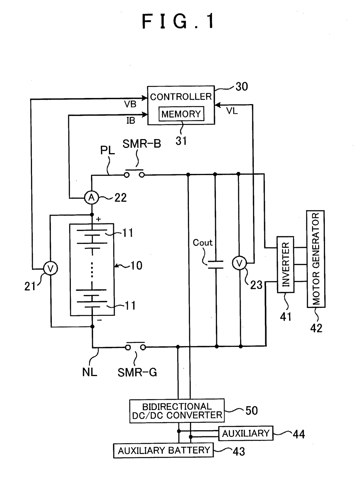
[0024]A battery system according to a first embodiment of the invention will be described. FIG. 1 is a view that shows the configuration of the battery system according to the present embodiment. The battery system according to the present embodiment is mounted on a vehicle. The vehicle is an electric vehicle or a hybrid vehicle. The electric vehicle includes only a main battery (described later) as a power source for propelling the vehicle. The hybrid vehicle includes an engine or a fuel cell in addition to the main battery (described later) as a power source for propelling the vehicle.

[0025]The main battery (which corresponds to a high-voltage battery according to the invention) 10 includes a plurality of single cells 11 connected in series with each other. A secondary battery, such as a nickel-metal hydride battery and a lithium ion battery, is used as each single cell 11. Instead of the secondary battery, an ele...


PUM


Abstract

A DC / DC converter is able to step down a voltage value of a high-voltage battery, and is able to step up a voltage value of a low-voltage battery. The low-voltage battery is a battery that provides a lower voltage value than the high-voltage battery. The DC / DC converter includes a transformer, a third diode and a reactor. The transformer includes a first coil and a second coil. The first coil is connected to the low-voltage battery. The second coil is connected to the high-voltage battery. An anode of the third diode is connected to one end of the first coil. One end of the reactor is connected to a cathode of the third diode, and the other end of the reactor is connected to a positive electrode terminal of the low-voltage battery.

Description

BACKGROUND OF THE INVENTION[0001]1. Field of the Invention[0002]The invention relates to a DC / DC converter that performs step-up operation and step-down operation, and an electrical storage system including the DC / DC converter.[0003]2. Description of Related Art[0004]A DC / DC converter described in Japanese Patent Application Publication No. 2012-182894 (JP 2012-182894 A) steps down an output voltage value of a high-voltage battery to a predetermined voltage value, and then charges a low-voltage battery with a stepped-down electric power. Here, in order to charge the low-voltage battery even when the voltage value of the high-voltage battery has decreased to a minimum voltage value as a result of a discharge of the high-voltage battery, the stepped-down voltage value should be higher than or equal to the voltage value of the low-voltage battery. In consideration of this point, the transformation ratio (the turns ratio of coils) of a transformer included in the DC / DC converter is set....

Claims


Application Information

Patent Timeline
Patent Type & Authority Applications(United States)
IPC IPC(8): H02M3/335B60L11/18B60L7/14H02P27/06B60L15/00
CPCH02M3/33584H02P27/06B60L15/007B60L7/14B60L2210/14B60L11/1861B60L11/1868B60L2210/12B60L11/1803B60L58/22B60L58/12B60L58/20B60L50/51H02M3/33569B60L2240/549B60L2240/547Y02T10/70Y02T10/64Y02T10/72
Inventor NISHI, YUJITANAKA, HIROMASAISHIGAKI, MASANORITOMURA, SHUJI
Owner TOYOTA JIDOSHA KK
Learn More