
Polymer for optical film, and optical film including the same

a technology of optical film and polymer, applied in the direction of optical elements, instruments, coatings, etc., can solve the problems of color shift, thickness retardation, and contrast ratio decreas

Active Publication Date: 2017-03-23
SAMSUNG ELECTRONICS CO LTD
View PDF2 Cites 3 Cited by
  • Summary
  • Abstract
  • Description
  • Claims
  • Application Information

AI Technical Summary

Benefits of technology

[0131]As such, the optical film according to the embodiment has good optical and thermal properties, and in an embodiment, has decreased CTE and high light transmittance, and thus may have very advantageous effects in manufacturing a display device, for example, a flexible substrate.
[0132]The optical film may be prepared by coating and casting the composition according to an embodiment on a substrate, followed by extending and curing to obtain a polyimide film. The method of manufacturing the film is also well known in the related art, and therefore, a detailed description thereof is omitted here.
[0133]According to still another embodiment, provided is an optical device including the optical film.
[0134]The optical device may be a liquid crystal device (“LCD”), an organic light emitting diode (“OLED”) or a complementary metal-oxide semiconductor (“CMOS”), and is not limited thereto.
[0135]Further, the optical film may be useful to prepare a flexible substrate due to its low CTE.
[0136]Hereinafter, the technology of this disclosure is described in detail with reference to examples. The following examples and comparative examples are not restrictive but are illustrative.EXAMPLESExamples 1 to 4Synthesis of Polyamic Acids

Problems solved by technology

In a liquid crystal display (“LCD”), which is a kind of non-emitting display device, elliptical polarization and light leakage may occur due to birefringence of liquid crystal and crossed polarizing plates in the display device, thereby decreasing contrast ratio and causing color shift.
As for the liquid crystal display, the device may become thicker due to the thickness of the liquid crystal, and thus the thickness retardation (“Rth”) may be a more serious than the in-plane retardation (“Re”).
However, since plastic substrates are unstable to heat, their properties need to be improved for use in the flexible displays.

Method used


Image

  • Polymer for optical film, and optical film including the same
  • Polymer for optical film, and optical film including the same
  • Polymer for optical film, and optical film including the same

Examples


examples 1 to 4

Synthesis of Polyamic Acids

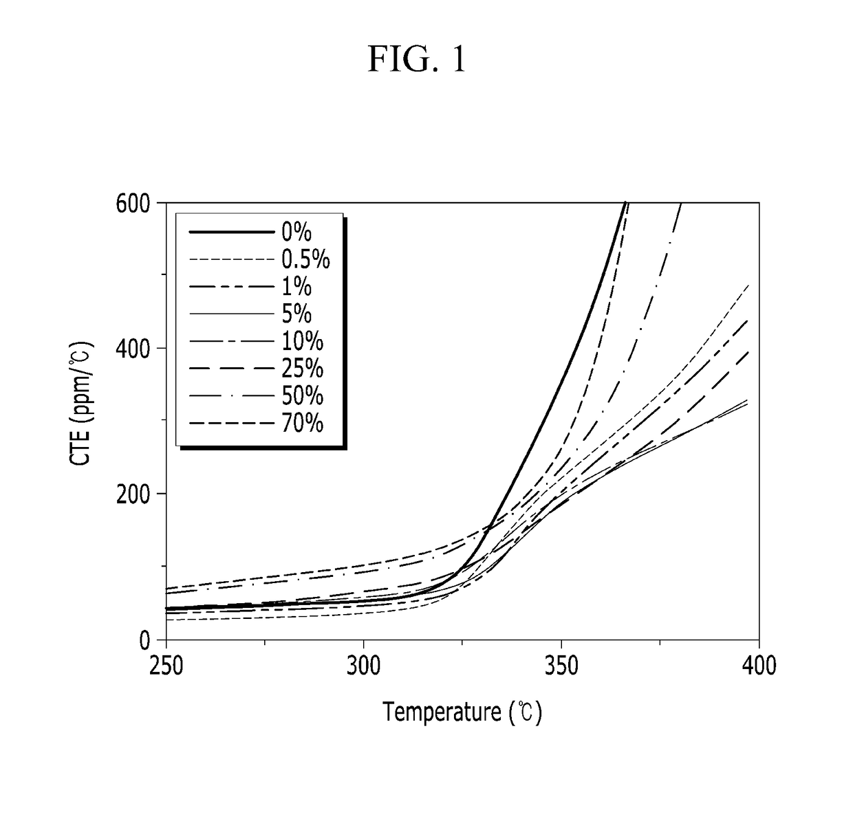
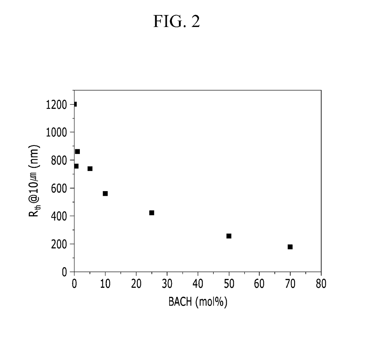
[0137]A dianhydride mixture of 80 mol % (3.34 g) of 3, 3′, 4, 4′-biphenyltetracarboxylic dianhydride (“BPDA”) and 20 mol % (0.62 g) of pyromellitic dianhydride (“PMDA”) and a diamine mixture of 2,2′-bis(trifluoromethyl)benzidine (“TFDB”) and 1,1′-bis(4-aminophenyl)cyclohexane (“BACH”) are mixed and polymerized to prepare polyimides. In the diamine mixture, the content of BACH is 0 mol % in Comparative Example 1, 0.5 mol % in Example 1, 1.0 mol % in Example 2, 5.0 mol % in Example 3, 10.0 mol % in Example 4, 25 mol % in Example 5, 50.0 mol % in Comparative Example 2, and 70.0 mol % in Comparative Example 3. 1 mole of the dianhydride mixture and 1 mole of the diamine mixture are reacted to prepare polyamic acid polymers.

[0138]Particularly, 40.4 ml of NMP as a solvent is added to a 250 liter reactor purged with N2 gas, and the diamine mixture of TFDB and BACH is added thereto at room temperature (25° C.). The reaction mixture is agitated at 100 revolutions pe...

synthesis example

Manufacturing Polyimide Films

[0139]The polyamic acids according to Examples 1 to 5 and Comparative Examples 1 to 3 are spin coated on a substrate, and maintained on a hot plate set on 80° C. for 30 minutes for drying. Then the films are put in a furnace, and are heat treated from room temperature to about 300° C. at a heating rate of 10° C. / minute to obtain polyimide films.

[0140]Further, in order to evaluate the films, the films are subject to further heat treatment from room temperature to 300° C. at a heating rate of 10° C. / minute, then maintained at 300° C. for 60 minutes to obtain required films.

experimental example

Evaluation of Properties of the Films

[0141]The film thickness, light transmittance at a specific wavelength, film thickness retardation (Rth), CTE at a specific temperature range, glass transition temperature (“Tg”), and 0.5% weight decrease temperature (“Td0.5”) and 1.0% weight decrease temperature (“Td1.0”) are measured, and the results are summarized in Table 1. The graphs showing changes of CTE and Rth of the films depending on the content of BACH are also shown in FIG. 1 and FIG. 2, respectively.

TABLE 1FilmthicknessTransmittance (%)RthCTE (ppm / ° C.)TgTd0.5Td1.0(μm)380~800 nm400 nm430 nm(nm)50~25050~30050~400(° C.)(° C.)(° C.)Comp.1088508212001113756323485.8524Exam. 1Exam. 188752817581113172331467.2505Exam. 2168861818601215152322468.8501Exam. 3168857797401720113323461.9483Exam. 4108842785602226114320445.6473Exam. 598625684203641148338424.2456Comp.168425542575055336344395.9418Exam. 2Comp.168321471785560664346391.1411Exam. 3

[0142]As shown from Table 1, the polyimide films prepared...


PUM

PropertyMeasurementUnit
light transmittanceaaaaaaaaaa
temperatureaaaaaaaaaa
mol %aaaaaaaaaa

Abstract

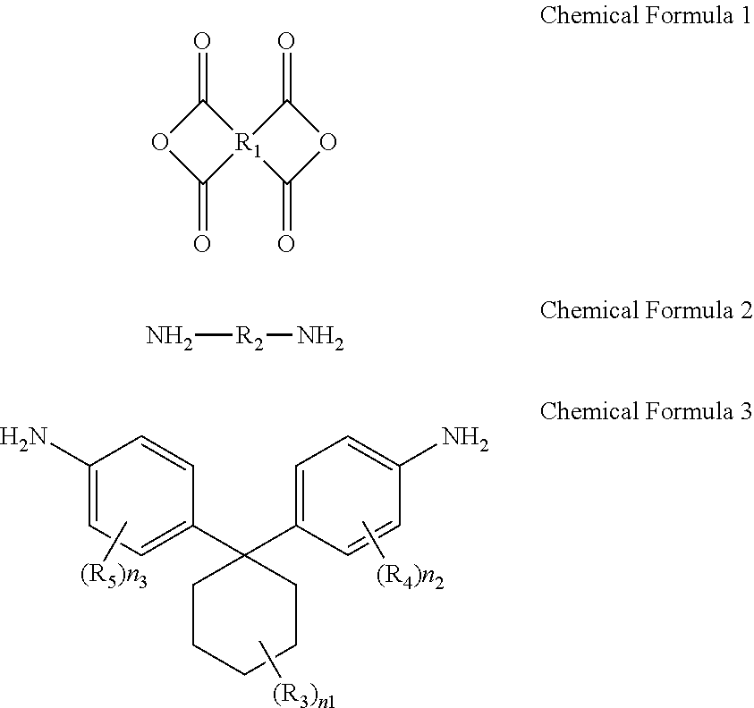
A composition for preparing an optical film, comprising a tetracarboxylic acid dianhydride represented by Chemical Formula 1, a first diamine represented by Chemical Formula 2, and a second diamine represented by Chemical Formula 3, wherein an amount of the second diamine represented by Chemical Formula 3 is equal to or less than 30 mol % based on the total amount of the first and second diamines:wherein, R1 to R5, n1 to n3 are defined in the specification.

Description

CROSS-REFERENCE TO RELATED APPLICATION[0001]This application is a division of U.S. patent application Ser. No. 14 / 341,969, filed on Jul. 28, 2014, which claims priority to Korean Patent Application No. 10-2013-0147626, filed on Nov. 29, 2013, and all the benefits accruing therefrom under 35 U.S.C. §119, the contents of which are incorporated herein in their entirety by reference.BACKGROUND[0002]1. Field[0003]This disclosure relates to a polymer for optical film, and to an optical film including the polymer.[0004]2. Description of the Related Art[0005]Flat panel displays may be classified into emitting display devices that emit light by themselves and non-emitting display devices that require separate light sources. Optical compensation films such as phase difference films may be often used for improving image quality of the flat panel displays.[0006]In an emitting display device, for example, an organic light emitting display, visibility and contrast ratio may be decreased due to re...

Claims


Application Information

Patent Timeline
Patent Type & Authority Applications(United States)
IPC IPC(8): C08G73/10C08J5/18
CPCC08G73/1067C08J2379/08C08J5/18C08G73/1042C09D179/08G02F1/133305G02F1/133634C08G73/06C08L79/04G02B1/04
Inventor JEON, HYUN JEONGSOHN, BYUNG HEE
Owner SAMSUNG ELECTRONICS CO LTD
Learn More