
Engine jetting out combustion gas as driving force

Inactive Publication Date: 2017-02-09
AMNEXT TECH INC
View PDF5 Cites 1 Cited by
  • Summary
  • Abstract
  • Description
  • Claims
  • Application Information

AI Technical Summary

Benefits of technology

The present invention provides an engine that ejects gas produced by combustion as a driving force, with an opening-closing apparatus that can control the flow of combustion gas inside the engine. This allows for high-temperature, high-pressure combustion gas, even if the volume of the engine does not change or compression using a piston or the like is not performed. The engine can use a circumferential flow-type impeller with a simple configuration to increase the flow rate of gas that rotates the impeller. The engine can also include a battery that stores power generated by the engine, a motor that is supplied with power generated by the engine, and tires driven by the motor. The engine can function as a windmill, generating power using the wind without using fuel when the car is running, to recharge the battery and improve fuel consumption during running.

Problems solved by technology

The combustion that occurs inside the combustion chamber may be deflagration or may be detonation.

Method used


Image

  • Engine jetting out combustion gas as driving force
  • Engine jetting out combustion gas as driving force
  • Engine jetting out combustion gas as driving force

Examples


Embodiment Construction

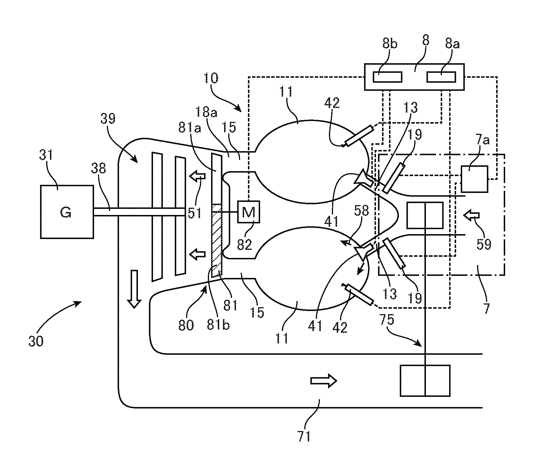
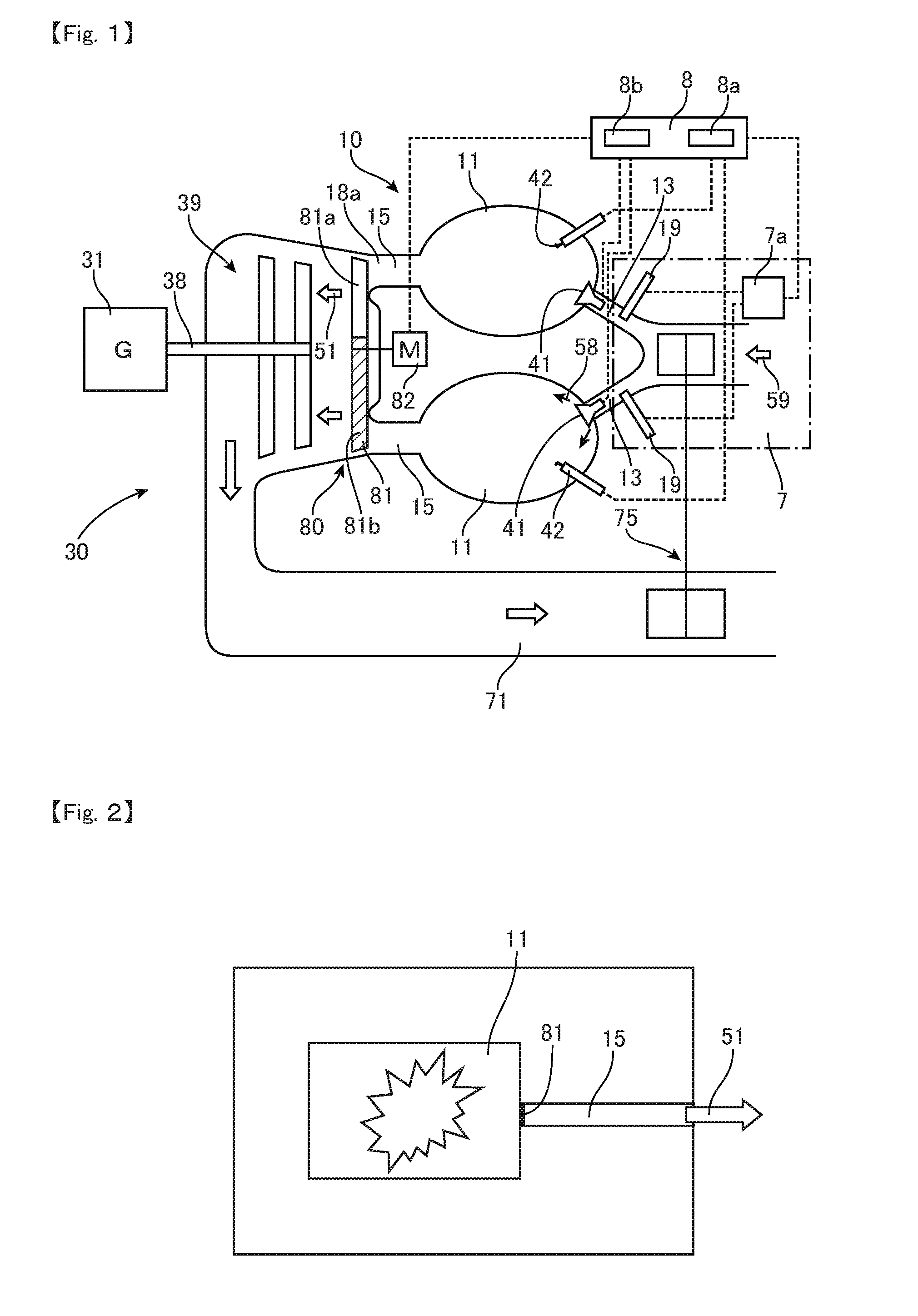
[0045]FIG. 1 depicts an engine 10 and a generator unit 30 that includes a generator 31 that is rotationally driven by the engine 10. The generator unit 30 further includes a fuel supplying system 7 that supplies the engine 10 with mixed gas for combustion, which includes fuel and air for combustion, and a control system 8 that controls the engine 10 including the timing of combustion. The control system 8 includes an ignition control unit 8a that controls the ignition timing of igniters 42 that are an ignition means and an opening-closing control unit 8 that controls valves and the like.

[0046]The engine 10 is a type that outputs (ejects, jets out, blasts) combustion gas (fired gas) 51 generated by combustion in combustion chambers 11 as the main driving force (power source). The engine 10 includes the combustion chambers 11 that have a fixed volume (fixed capacity), a fuel supplying paths (first routes, supply ports) 13 that supply gas (mixed gas) 58, which is produced by mixing fue...


PUM


Abstract

An engine (10) that jets out combustion gas as a driving force is provided. The engine (10) includes a combustion chamber (11), a fuel supplying path (13) that mixes fuel and air and supplies to the combustion chamber (11), an igniter (42) that ignites the mixed gas in the combustion chamber (11), a gas ejecting path (15) that ejects combustion gas (51) from the combustion chamber (11) though a nozzle (18a); and an opening-closing apparatus (80) that opens and closes the gas ejecting path (15). The gas ejecting path (15) is opened by the opening-closing apparatus (80) immediately before ignition, simultaneously with ignition, or immediately after ignition.

Description

TECHNICAL FIELD[0001]The present invention relates to an engine that has a combustion chamber and ejects combustion gas as a driving force.BACKGROUND ART[0002]Japanese Laid-open Patent Publication No. 2007-298013 discloses a rotary engine that obtains improved thermal efficiency. This rotary engine is constructed by housing a substantially triangular rotor in a cocoon-shaped housing that has an inner circumferential surface in the form of a trochoidal curve. In the housing, an intake pipe and an exhaust pipe are connected so as to be continuous, with the base ends thereof connected to each other so as to be continuous and sealed off from external space. Cooled regions that are cooled by a cooling mechanism and heated regions that are heated by a heating mechanism are formed on the inner circumferential surface of the housing. In each of the three working chambers formed between the housing and the rotor, gas drawn in from the intake pipe is cooled so as to contract by the cooled reg...

Claims


Application Information

Patent Timeline
IPC IPC(8): B60W20/00F02C3/14B60L11/12B60W10/08B60W10/26F01D15/10B60W10/06B60L50/15
CPCB60W20/00F01D15/10F02C3/14B60W10/06B60W10/08Y10S903/93B60L11/12F05D2220/32F05D2240/35F05D2240/128B60W10/26F02C5/12F02C6/20B60K3/04B60K2016/006Y02T10/90B60K5/00B60L50/15Y02T50/60
Inventor OHISHI, YASUTOSHI
Owner AMNEXT TECH INC
Learn More