
Biometric identification apparatus

Inactive Publication Date: 2017-01-26
EGALAX EMPIA TECH INC
View PDF11 Cites 16 Cited by
  • Summary
  • Abstract
  • Description
  • Claims
  • Application Information

AI Technical Summary

Benefits of technology

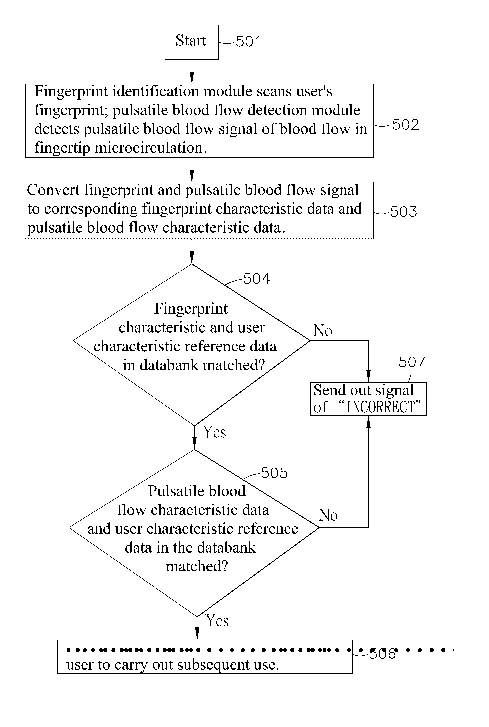
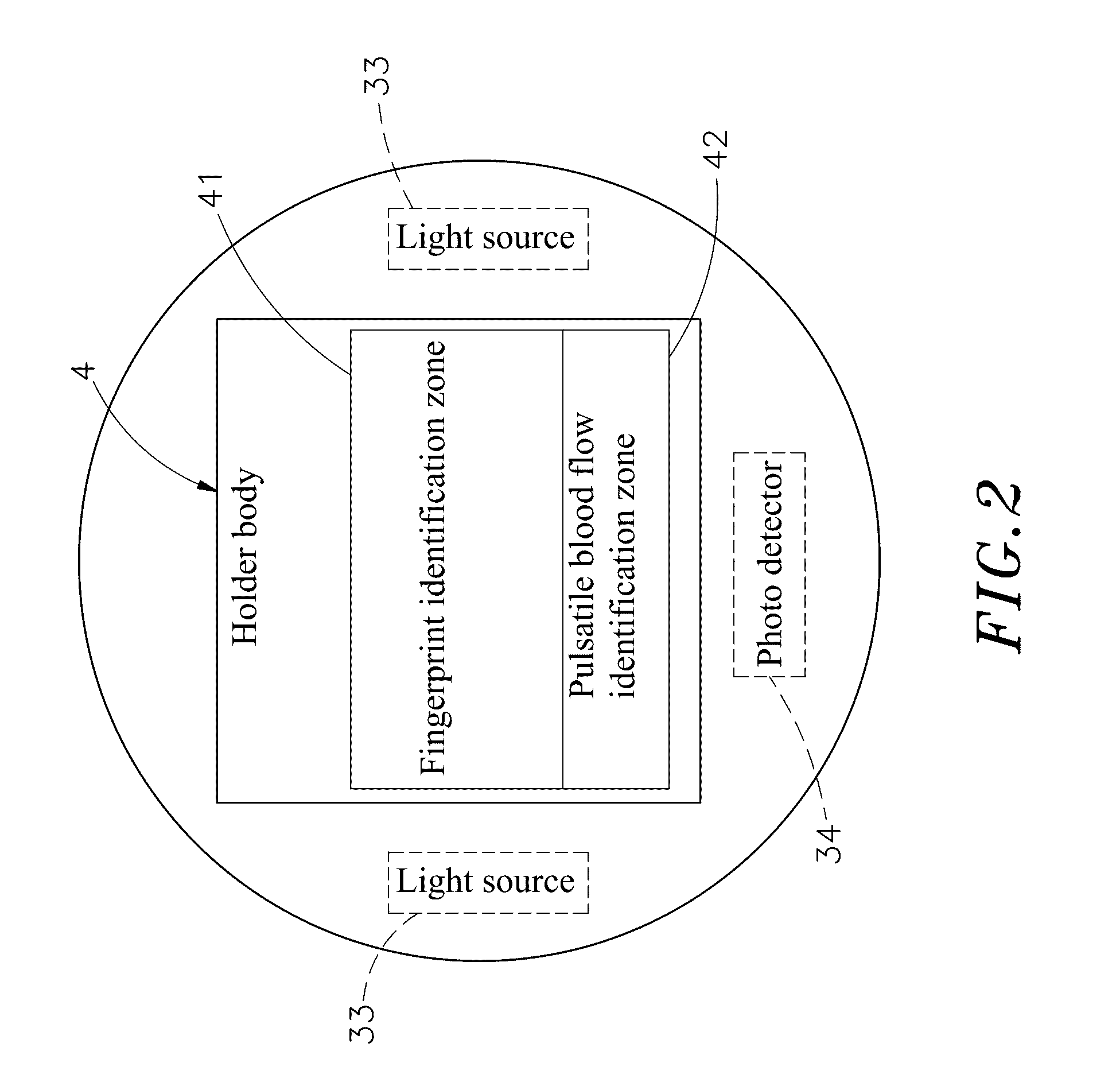
The present invention provides a biometric identification apparatus that can detect a user's fingerprint and pulsatable blood flow signals for security access control. This increases the difficulty of cracking, providing better anti-theft function. The apparatus can also record the unique pulsatile blood flow waveform of every person, enhancing the precision of matching. Additionally, the combined surface area of the fingerprint and pulsatile blood flow identification zones is approximately equal to the surface area of the finger pad of one single finger, making detection faster and more convenient.

Problems solved by technology

When markets have become more aware of security issues, the convention locks, combination blocks or locks applied to mobile phones are vulnerable, manufacturers keep creating security technologies in different ways.
Thus, an evil person can easily collect fingerprints left behind by a person for creating forged fingerprints.
However, these monitoring devices commonly have the drawbacks of large size and high power consumption, thus, the mobility and power supply applications of these monitoring devices are restricted.
Because mobile electronic devices have become popular and mobile electronic device security problem is an issue of concern, the application of fingerprint identification technology can be seen in mobile phones.
However, conventional fingerprint identification designs are still vulnerable to hackers.

Method used


Image

  • Biometric identification apparatus
  • Biometric identification apparatus
  • Biometric identification apparatus

Examples


Embodiment Construction

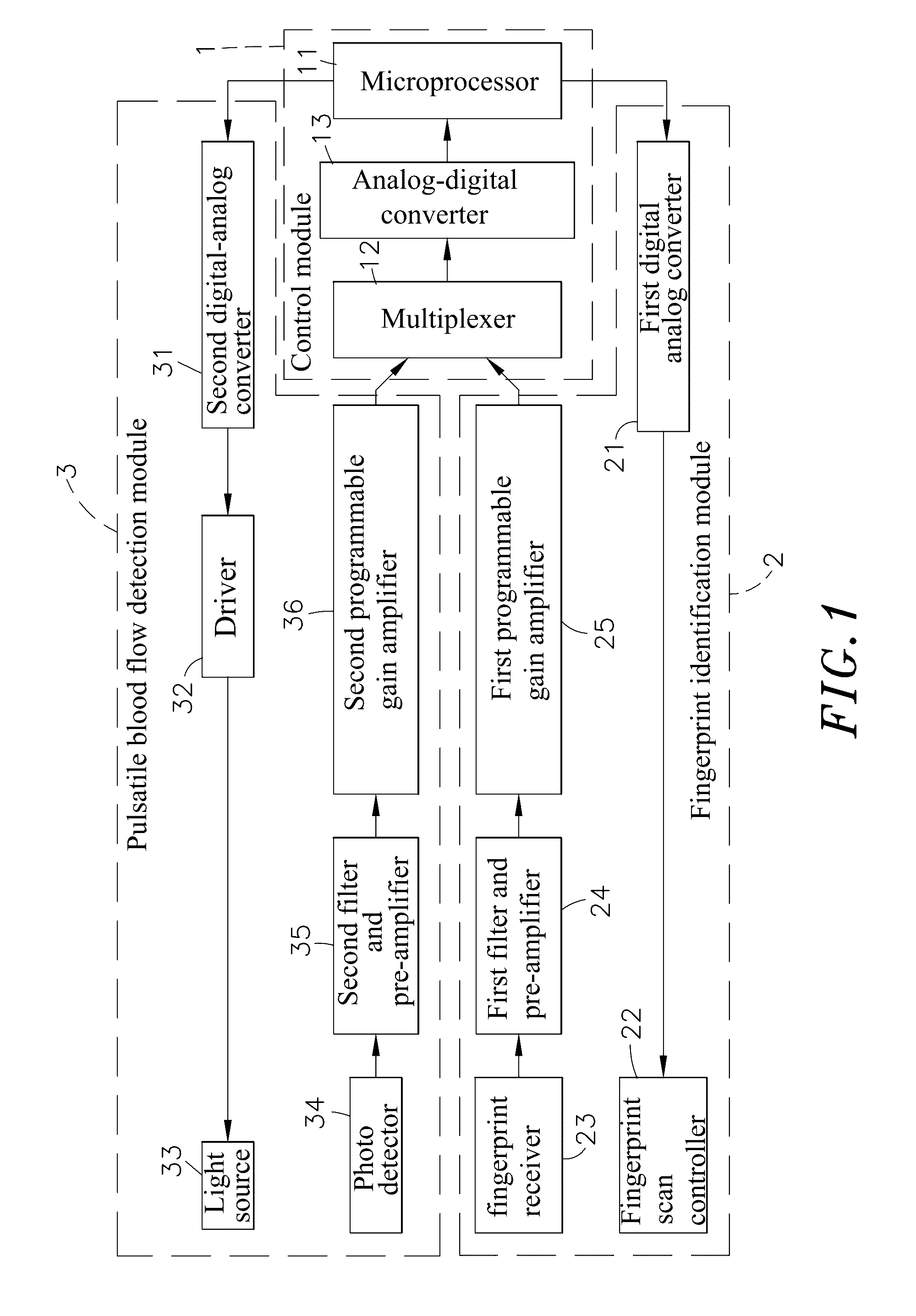
[0018]Referring to FIGS. 1 and 2, a biometric identification apparatus in accordance with the present invention generally comprises a control module 1, a fingerprint identification module 2, a pulsatile blood flow detection module 3 and a holder body 4.

[0019]The control module 1 comprises a microprocessor 11, a multiplexer 12 and an analog-digital converter 13. The analog-digital converter 13 is electrically connected between the microprocessor 11 and the multiplexer 12. The multiplexer 12 is adapted for receiving signals from the fingerprint identification module2 and the pulsatile blood flow detection module 3 and transmitting received signals to the analog-digital converter 13. The analog-digital converter 13 is adapted for converting each inputted analog signal to a corresponding digital signal and then transmitting the converted digital signal to the microprocessor 11. The control module 1 is adapted for controlling the fingerprint identification module 2 and the pulsatile bloo...


PUM


Abstract

A biometric identification apparatus includes a control module, a fingerprint identification module including a fingerprint scan controller and a fingerprint receiver, a pulsatile blood flow detection module including one or multiple light sources and a photo detector, and a holder body defining a fingerprint identification zone and a pulsatile blood flow identification zone. In application, the user simply needs to press the fingertip of one single finger on the fingerprint identification zone and pulsatile blood flow identification zone of the holder body so that the biometric identification apparatus can detect user's fingerprint and pulsatile blood flow signals, fetch and convert characteristic data of detected signals, and then match fetched fingerprint and pulsatile blood flow characteristic data with respective reference data for security access control. The application of this dual-biometric identification technology greatly increases the cracking difficulty, achieving better anti-theft function.

Description

[0001]This application claims the priority benefit of Taiwan patent application number 104123708, filed on Jul. 22, 2015BACKGROUND OF THE INVENTION[0002]1. Field of the Invention[0003]The present invention relates to biometric identification technology and more particularly, to a biometric identification apparatus that employs dual-biometric identification technology to identify fingerprint and pulsatile blood flow signals for security access control, enhancing the anti-theft effect.[0004]2. Description of the Related Art[0005]When markets have become more aware of security issues, the convention locks, combination blocks or locks applied to mobile phones are vulnerable, manufacturers keep creating security technologies in different ways. At this time, the current maturity of several biometric identification technologies has get manufacturers' and consumers' attention. The common biometric identification technologies use different sensors to detect different biometric features such ...

Claims


Application Information

Patent Timeline
IPC IPC(8): G06K9/00G06F21/32
CPCG06K9/00013G06F21/32G06K2009/00939G06K9/00087G06K9/00906G06K9/00892G06F21/83G06V40/1365G06V40/70G06V40/15G06V40/45
Inventor LIN, PO-CHUAN
Owner EGALAX EMPIA TECH INC
Learn More