
RFI/EMI Shielding Enclosure Containing Wireless Charging Element for Personal Electronic Devices Security

a wireless charging element and wireless charging technology, applied in the field of security devices, can solve the problems of workplace damage to productivity, inability to allow access to mobile phones, and ineffective traditional solutions to prevent malicious or inadvertent use of smartphones, etc., to achieve useful operation, enhance security, and save battery energy

Active Publication Date: 2016-12-22
SERENE DEVICES LLC
View PDF41 Cites 74 Cited by
  • Summary
  • Abstract
  • Description
  • Claims
  • Application Information

AI Technical Summary

Benefits of technology

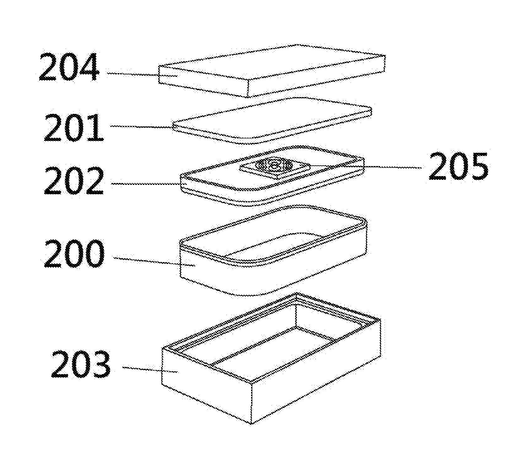
The invention is a security enclosure for smartphones that can protect it from unauthorized theft and disclosure of confidential business information or invasions of personal privacy. The enclosure has EMI / RFI shielding ability and a charging element to charge the battery of the smartphone. The placement of the charging element within the enclosure enhances its efficiency. This combination of features provides users with two forms of simplicity: fewer wires, with no need for a charger, and disconnecting, with fewer distractions and mitigation of threats to business security and personal privacy.

Problems solved by technology

In order to prevent confidential business materials from being compromised, many organizations do not allow access to mobile phones during meetings.
However traditional solutions are not entirely effective in preventing malicious or inadvertent use of a smartphone to record confidential business information.
In different scenarios, employee use of smartphones in meetings can distract from their attention to important discussions, or such use in the workplace can be detrimental to productivity.
In the home, malicious or inadvertent use of a smartphone as a recording device can bring about an invasion of personal privacy.
Family members' persistent use of smartphones may also distract from optimal attention to personal relations, as in the case of parental inattention to children.
However, the smartphone will lose battery energy within the enclosure due to the smartphone continuously trying to search for an RF signal station.

Method used


Image

  • RFI/EMI Shielding Enclosure Containing Wireless Charging Element for Personal Electronic Devices Security
  • RFI/EMI Shielding Enclosure Containing Wireless Charging Element for Personal Electronic Devices Security
  • RFI/EMI Shielding Enclosure Containing Wireless Charging Element for Personal Electronic Devices Security

Examples


first embodiment

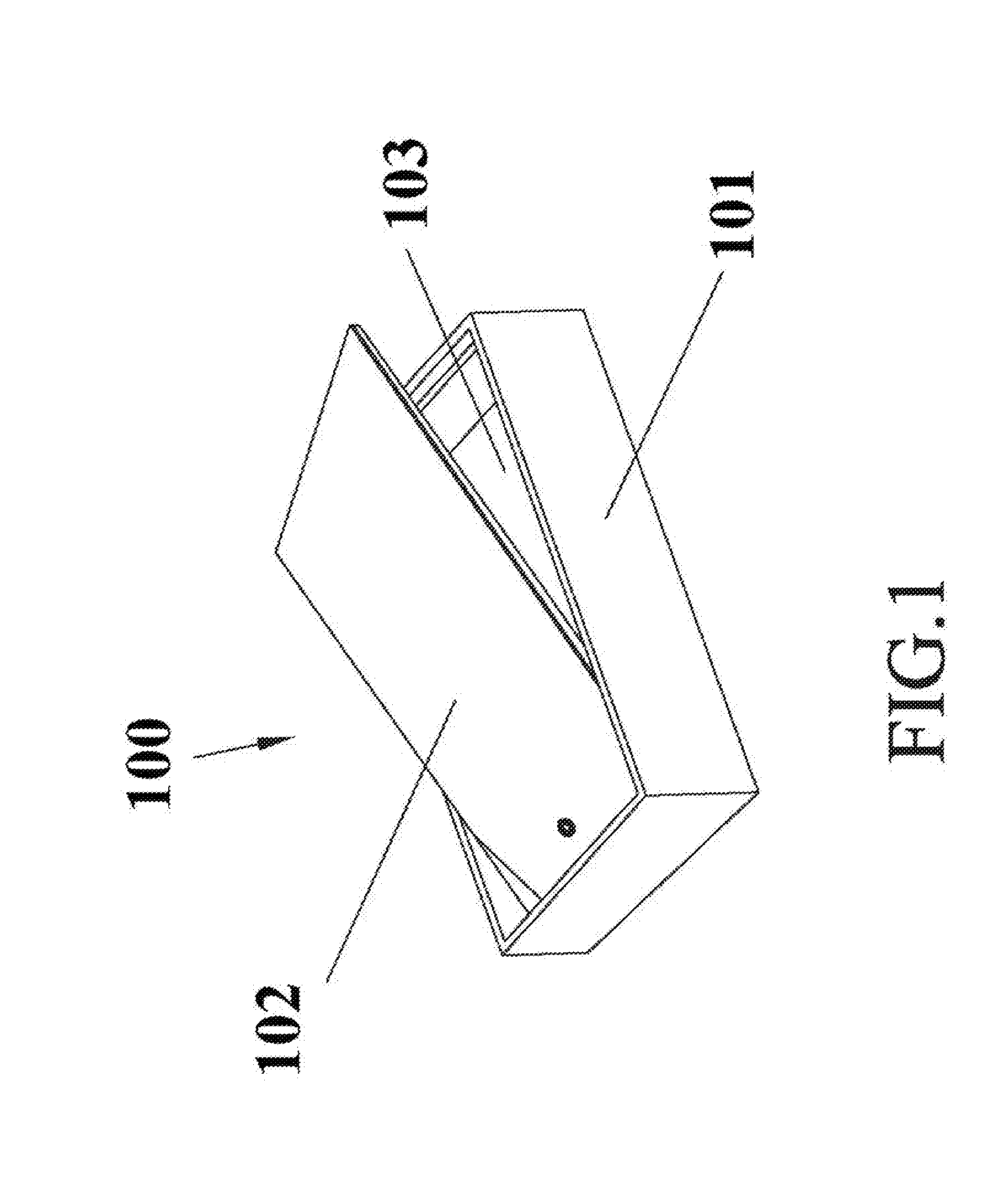
[0041]FIG. 1 illustrates an EMI / RFI shielding enclosure according to the present invention. In this embodiment, the EMI / RFI shielding enclosure 100 is consisted of a lower enclosure 101 and an upper lid 102, and the upper lid 102 is therefore structurally engaging with (and covering) the whole lower enclosure 101. The EMI / RFI shielding enclosure 100 is for example a Faraday cage. The lower enclosure 101 has four sidewalls and a base portion. In one embodiment, the lower enclosure 101 defines a first interlocking portion at two inner lateral sides of the four sidewalls of lower enclosure 101 to interlock a second interlocking portion at two lateral sides of the upper lid 102 by mechanical latches or screws such that the upper lid 102 is capable of pivoting along a parallel axis by pushing vertically to allow for easy access open / close by a user, and the lower enclosure 101 defines a concave space 103 for one electronic device (such as smartphone) disposed on the base portion of the l...

second embodiment

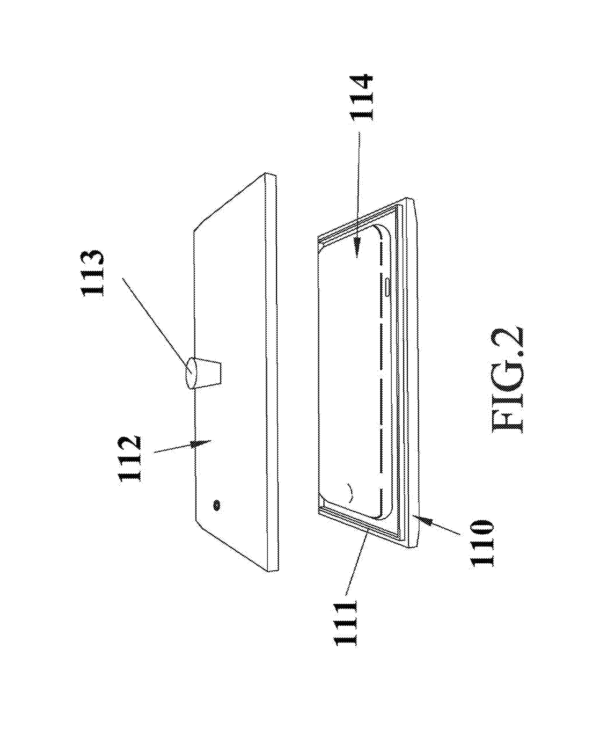
[0047]FIG. 2 illustrates the security enclosure according to the present invention. In this embodiment, the EMI / RFI shielding enclosure is consisted of a lower enclosure 110, an EMI / RFI shielding gasket 111 and an upper lid 112, and the EMI / RFI shielding gasket 111 is configured between the lower enclosure 110 and the upper lid 112 to ensure that the gap does not reduce shielding effectiveness. In this embodiment, the upper lid 112 is configured with a lift pin 113 fixed onto the upper lid 112 for lift-on / lift-off the EMI / RFI shielding enclosure. A concave space (within the lower enclosure 110) is defined between the lower enclosure 110 and the upper lid 112 for receiving one electronic device 114, such as smartphone, which may be disposed on the base portion of the lower enclosure 110. The smartphone 114 can be directly manually disposed on the base portion of the lower enclosure 110, followed by holding the lift pin 113 of the upper lid 112 to close (lift-on) the EMI / RFI shielding...

third embodiment

[0052]FIG. 3 illustrates an EMI / RFI shielding enclosure according to the present invention. In this embodiment, the EMI / RFI shielding enclosure 120 is consisted of a lower enclosure 121 and an upper lid 122, and the upper lid 122 is structurally engaging with (and covering) the whole lower enclosure 121. The EMI / RFI shielding enclosure 120 is a Faraday cage. The lower enclosure 121 has four sidewalls and a base portion. The EMI / RFI shielding enclosure 120 is a multiple device holder, and therefore the lower enclosure 121 defines a receiving (accommodating) space 123 for multiple electronic devices (such as multiple smartphones) 124 disposed on the base portion of the lower enclosure 121. The shape of the enclosure 120 shown in FIG. 3 takes the form of a rectangular; however the invention is not limited in this respect. Multiple smartphones 124 can be directly manually disposed on the base portion of the lower enclosure 121, followed by pushing rear end of the upper lid 122 for slidi...


PUM


Abstract

The invention provides an electromagnetically shielded enclosure for personal electronic device security, comprising a lower enclosure having a receiving space for at least one electronic devices disposed on a base portion of the lower enclosure. An upper lid is structurally engaging with the whole lower enclosure to form an electromagnetically shielding structure. A wireless charging element is configured on the lower enclosure for wirelessly charging to provide power to at least one electronic device.

Description

CROSS-REFERENCE TO RELATED APPLICATIONS[0001]This application claims the benefit of the U.S. provisional patent application No. 62 / 181,259, filed Jun. 18, 2015.TECHNICAL FIELD[0002]The present invention generally relates to a security apparatus, more particularly, to an RFI / EMI shielding enclosure containing a wireless charging element for personal electronic devices.BACKGROUND OF RELATED ARTS[0003]Advances in smartphone technology have reached a point such that for many users such smartphones provide their primary access to the internet. It may even come to pass in the foreseeable future that such smartphones may replace to some extent standard desktop or laptop computer systems. Their small size allows these devices to be always accessible, becoming an invaluable tool for a variety of applications including social networking, GPS-based navigation, entertainment, communication in a variety of media, etc. Smartphones need an effective energy management solution. The core requirement...

Claims


Application Information

Patent Timeline
Patent Type & Authority Applications(United States)
IPC IPC(8): H02J7/00H05K9/00H02J7/02H05K5/02
CPCH02J7/0042H05K5/0239H05K5/0221H02J7/025H05K9/0049H02J50/10H02J50/402H02J7/0044H02J7/0013
Inventor KVOLS, DAVID KRISTIAN
Owner SERENE DEVICES LLC
Learn More