
Thermal energy network

a technology of thermal energy network and thermal energy, applied in the direction of combined combustion mitigation, lighting and heating apparatus, heating types, etc., can solve the problems of increasing capital costs, increasing running costs, and reducing thermal efficiency

Inactive Publication Date: 2016-11-17
GREENFIELD MASTER IPCO
View PDF5 Cites 13 Cited by
  • Summary
  • Abstract
  • Description
  • Claims
  • Application Information

AI Technical Summary

Benefits of technology

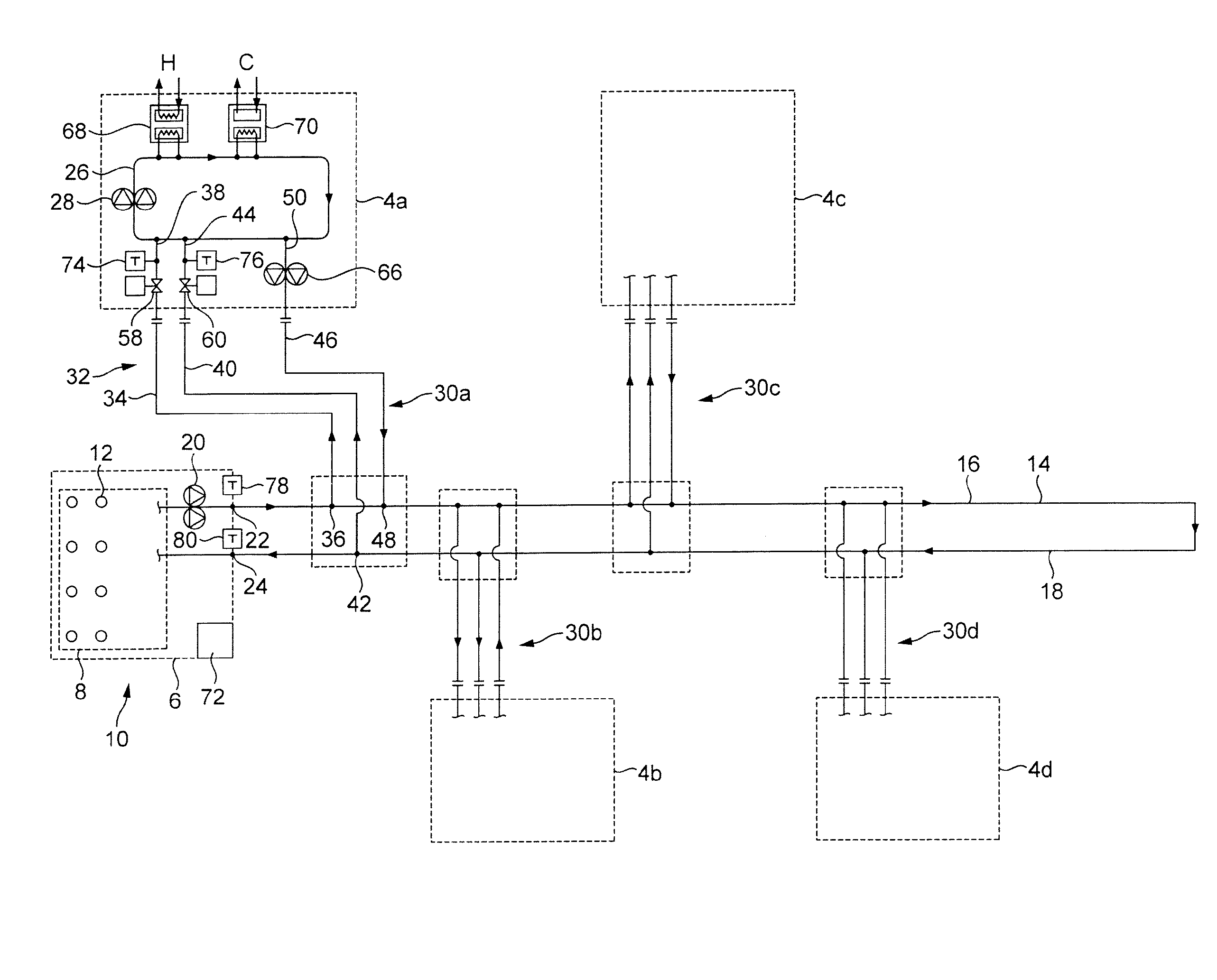
The patent describes a control system that helps balance the temperature of a primary circuit loop by adding a positive or negative thermal input from the energy center. This system compensates for any energy lost or gained from the heating or cooling of the loads connected to the loop. Its technical effect is to ensure a consistent temperature control in the primary circuit loop.

Problems solved by technology

Such known district heating networks suffer from the problem that a high fluid temperature increases the capital costs, for example because of the need for thermal insulation along the loop, and increases the running costs, and lowers the thermal efficiency, because of high residual thermal losses and temperature drops across the network.
The major problem associated with traditional district heating networks is low utilisation rate; the return on investment in district networks is only can be generated during an intensive active heating season when there is a demand for heating.
Therefore, in countries with a rather mild climate settings district heating schemes constitute a rather low share of the total heating demand nationwide.
Furthermore, ongoing maintenance of district heating networks is a heavy burden even in countries where the active heating season lasts around six months.
This is related to the same problem with low utilisation of an extensive asset such as a district or city wide heating network.
In the UK, where the climate is relatively mild, the ongoing maintenance cost associated with maintaining the network is equal to the problem of high capital investment.
Again, there are high capital costs because of the need for thermal insulation along the loop, increased running costs, and low thermal efficiency.

Method used


Image

  • Thermal energy network
  • Thermal energy network
  • Thermal energy network

Examples


second embodiment

[0072]Referring to FIG. 3, there is shown a geothermal energy network 102 interconnecting a plurality of buildings 104a, 104b, 104c, 104d in accordance with the present invention.

first embodiment

[0073]This embodiment is modified as compared to the first embodiment by providing modified connections 30a, 30b, 30c, 30d to the primary circuit loop 14. The connections 30a, 30b, 30c, 30d each include four working fluid lines, two lines connecting the user circuit loop 26 to the upstream outflow line 16 and two lines connecting the user circuit loop 26 to the downstream return line 18.

[0074]In the illustrated embodiment, each connection 30a, 30b, 30c, 30d comprises four working fluid lines. A first working fluid line 134 has an inlet 136 connected to the upstream outflow line 16 and an outlet 138 connected to the user circuit loop 26. A second working fluid line 140 has an outlet 142 connected to the downstream return line 18 and an inlet 144 connected to the user circuit loop 26. A third working fluid line 146 has an inlet 148 connected to the downstream return line 18 and an outlet 150 connected to the user circuit loop 26. A fourth working fluid line 152 has an outlet 154 conne...


PUM


Abstract

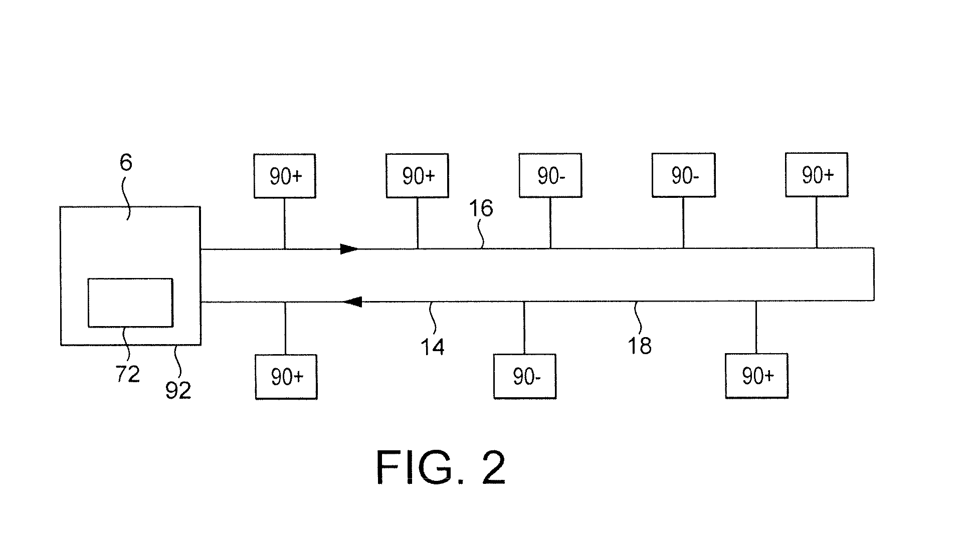
A district energy network interconnecting a plurality of thermal loads and for redistributing thermal energy therebetween, the network comprising: a primary circuit loop for working fluid, at least two thermal loads thermally connected to the primary circuit loop, at least one of the thermal loads being capable of taking heat from the primary circuit loop and at least one of the thermal loads being capable of rejecting heat into the primary circuit loop, an energy centre connected to the loop and capable of acting as a heat source or a heat sink, and a control system adapted to provide to the primary circuit loop a positive or negative thermal input from the energy centre as a balancing thermal input to compensate for net thermal energy lost to or gained from the at least two thermal loads by the primary circuit loop.

Description

FIELD OF THE INVENTION[0001]The present invention relates to a thermal energy network interconnecting a plurality of thermal loads and to a method of providing thermal energy to a plurality of thermal loads. The present invention has particular application to the provision of thermal energy using a district network to an estate of residential, industrial and / or commercial buildings.BACKGROUND OF THE INVENTION[0002]It is known to connect a thermal energy system to a plurality of buildings to provide heating to the buildings. This arrangement is known in the art as a “district heating system” or “heating network”. Buildings are connected at respective connection points to a single loop conveying high-temperature fluid, namely water, around the loop or series of loops and could serve all heating needs within certain areas or the entire cities with its suburbs. A typical heat transfer media is steam or fluid with flow temperature ranging from 70 to 90° C. The steam or hot water is gener...

Claims


Application Information

Patent Timeline
IPC IPC(8): F24D10/00E03B7/02E03B7/07F24D19/10
CPCF24D10/003E03B7/07E03B7/02F24D19/1015F24D10/006F24D2200/11Y02B10/40F24D10/00Y02E20/14Y02B30/17
Inventor ZAYNULIN, DMITRIYARDIS, MICHAELSTICKNEY, KEVINDAVIS, GREGORYLEIPER, ALBANHAYES, JOHN
Owner GREENFIELD MASTER IPCO
Learn More