Methods for surface preparation of sputtering target
a surface preparation and target technology, applied in the field of surface preparation of sputtering target, can solve the problems of reducing device yield, grinding lines, scratches, embedded impurities, etc., and achieves high fracture roughness, high wear resistance, and smooth surface
- Summary
- Abstract
- Description
- Claims
- Application Information
AI Technical Summary
Benefits of technology
Problems solved by technology
Method used
Image
Examples
example 1
ed Ruthenium (Ru) Target
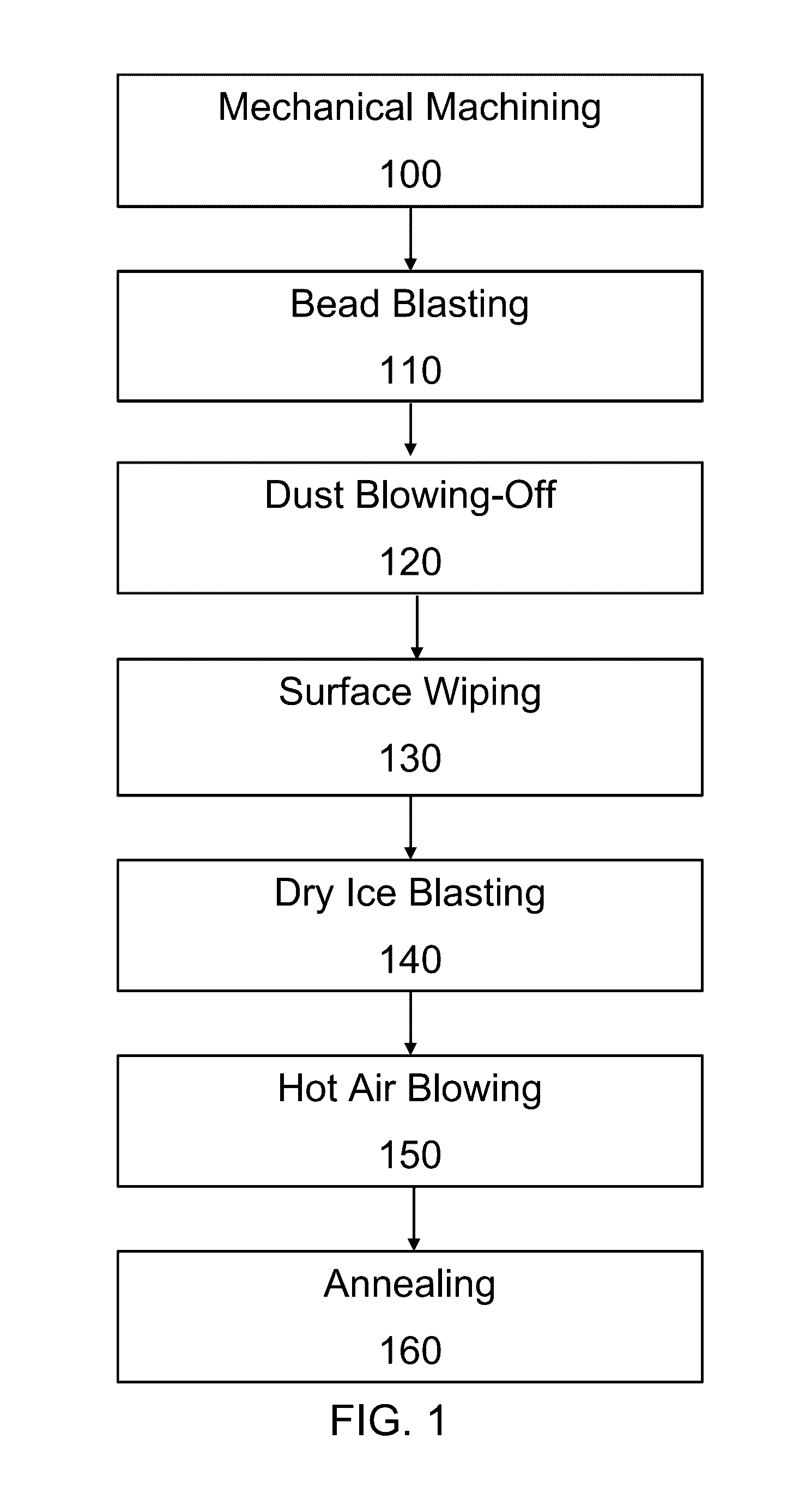
[0051]A ruthenium (Ru) sputtering target with diameter of 165 mm and thickness of 3.8 mm was sintered and then subjected to a mechanical machining and mechanical grinding step. This was followed by bead blasting with spherical zirconia beads.
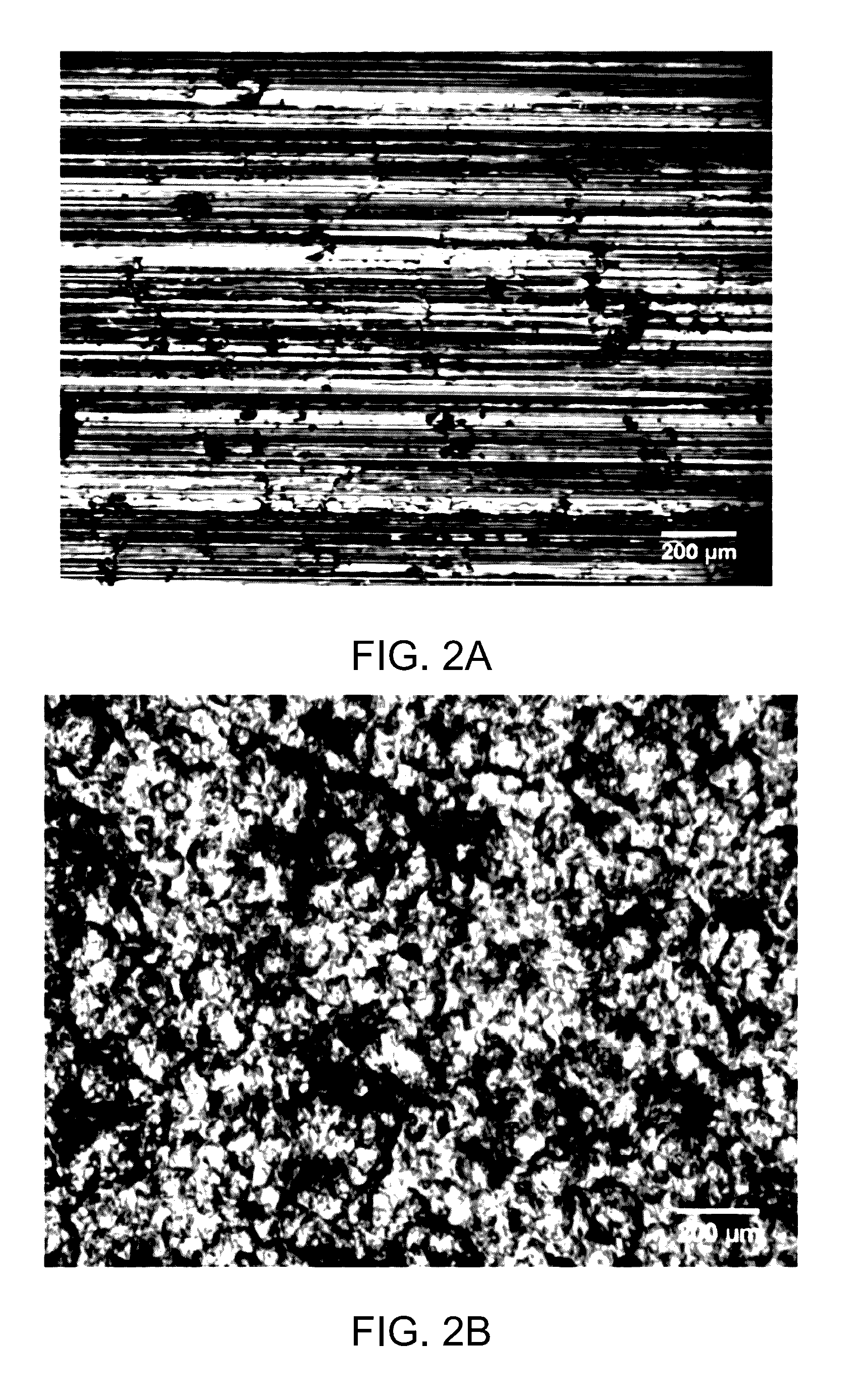
[0052]FIG. 2A is an optical micrograph of the sputtering target surface after machining, i.e. prior to bead blasting. Grinding-induced defects such as surface micro cracks, grinding marks, contamination, and other surface defects were observed on the as-ground surface. The surface roughness after grinding was anisotropic. In the direction parallel to the grinding direction, the surface roughness was 3-7 Ra, however, the surface roughness was 8-12 Ra in the direction transverse to the grinding direction.
[0053]FIG. 2B is an optical micrograph of the sputtering target surface after bead blasting. The grinding-induced defects were removed by the bead blasting. A homogeneous and clean surface was also observed after blasting. ...
example 3
ering Target
[0062]A magnesium oxide (MgO) sputtering target produced via sintering with a diameter of 175 mm and thickness of 5 mm was subjected to a mechanical grinding step followed by bead blasting with spherical zirconia beads.
[0063]FIG. 4A is an optical micrograph of the sputtering target surface after mechanical machining. Machining-induced micro cracks and clustered MgO particles are observed. The surface roughness was 31-37 Ra in the direction parallel to the grinding lines, and 35-39 Ra in the direction perpendicular to the grinding lines.
[0064]FIG. 4B is an optical micrograph of the sputtering target surface after bead blasting. The surface roughness became isotropic (around 98-126 Ra) in two cross directions. While the surface roughness increased after bead blasting, the machining-induced lines were removed by the bead blasting. Clustered and loosely bonded particles have also been wiped off. Such surface structure and features are thought to be beneficial to reduce initi...
PUM
| Property | Measurement | Unit |
|---|---|---|
| particle size | aaaaa | aaaaa |
| pressure | aaaaa | aaaaa |
| angle | aaaaa | aaaaa |
Abstract
Description
Claims
Application Information
 - R&D
- Intellectual Property
- Life Sciences
- Materials
- Tech Scout
- Unparalleled Data Quality
- Higher Quality Content
- 60% Fewer Hallucinations
Browse by: Latest US Patents, China's latest patents, Technical Efficacy Thesaurus, Application Domain, Technology Topic, Popular Technical Reports.
© 2025 PatSnap. All rights reserved.Legal|Privacy policy|Modern Slavery Act Transparency Statement|Sitemap|About US| Contact US: help@patsnap.com


