
Intravenous splint cover and associated methods

Active Publication Date: 2016-11-03
WILBORN MARIE ANDREA I
View PDF0 Cites 1 Cited by
  • Summary
  • Abstract
  • Description
  • Claims
  • Application Information

AI Technical Summary

Benefits of technology

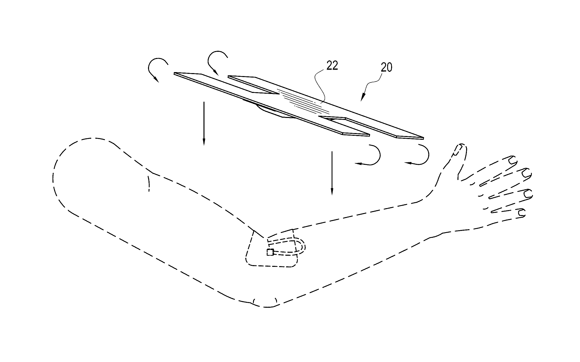
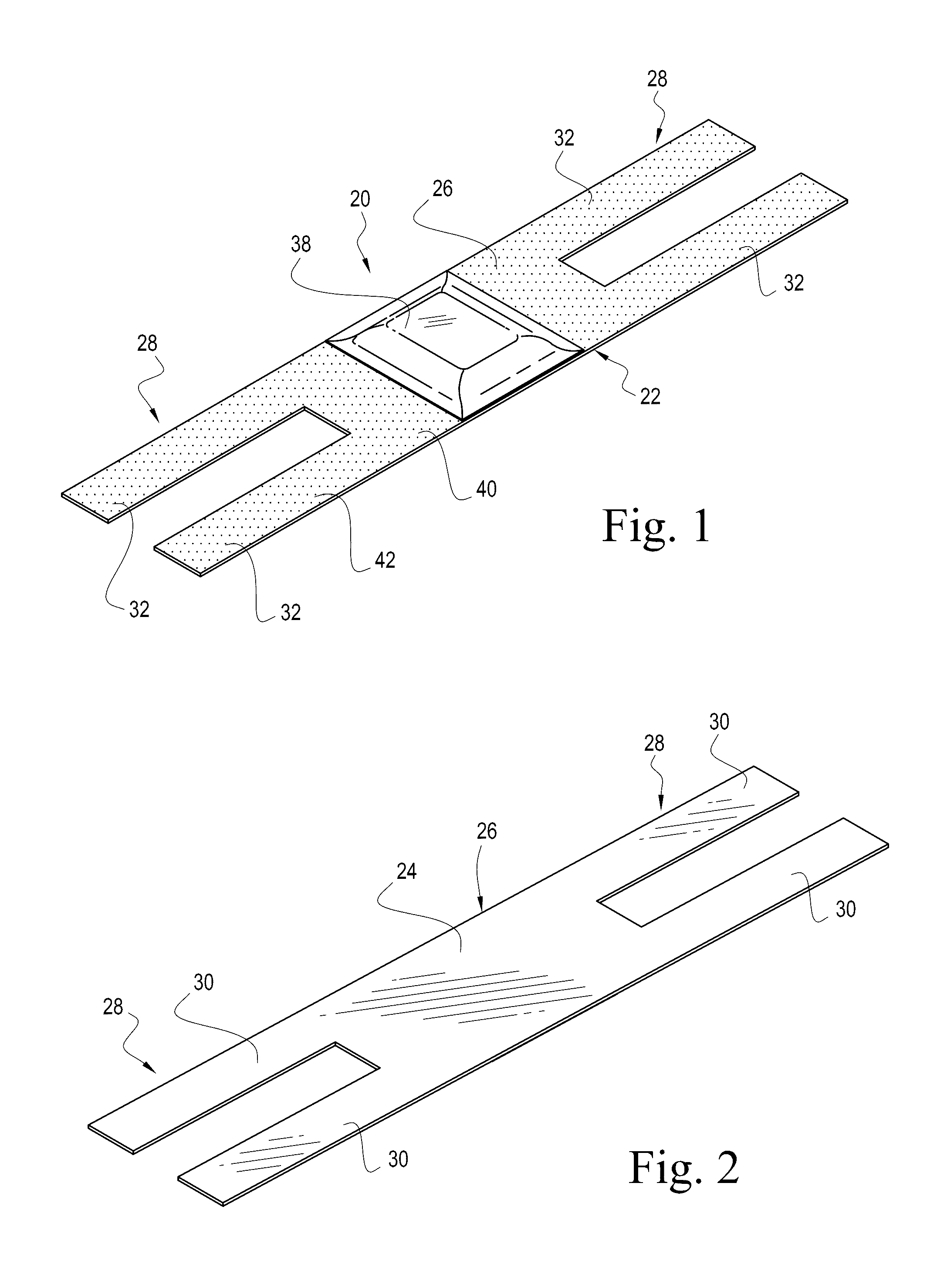
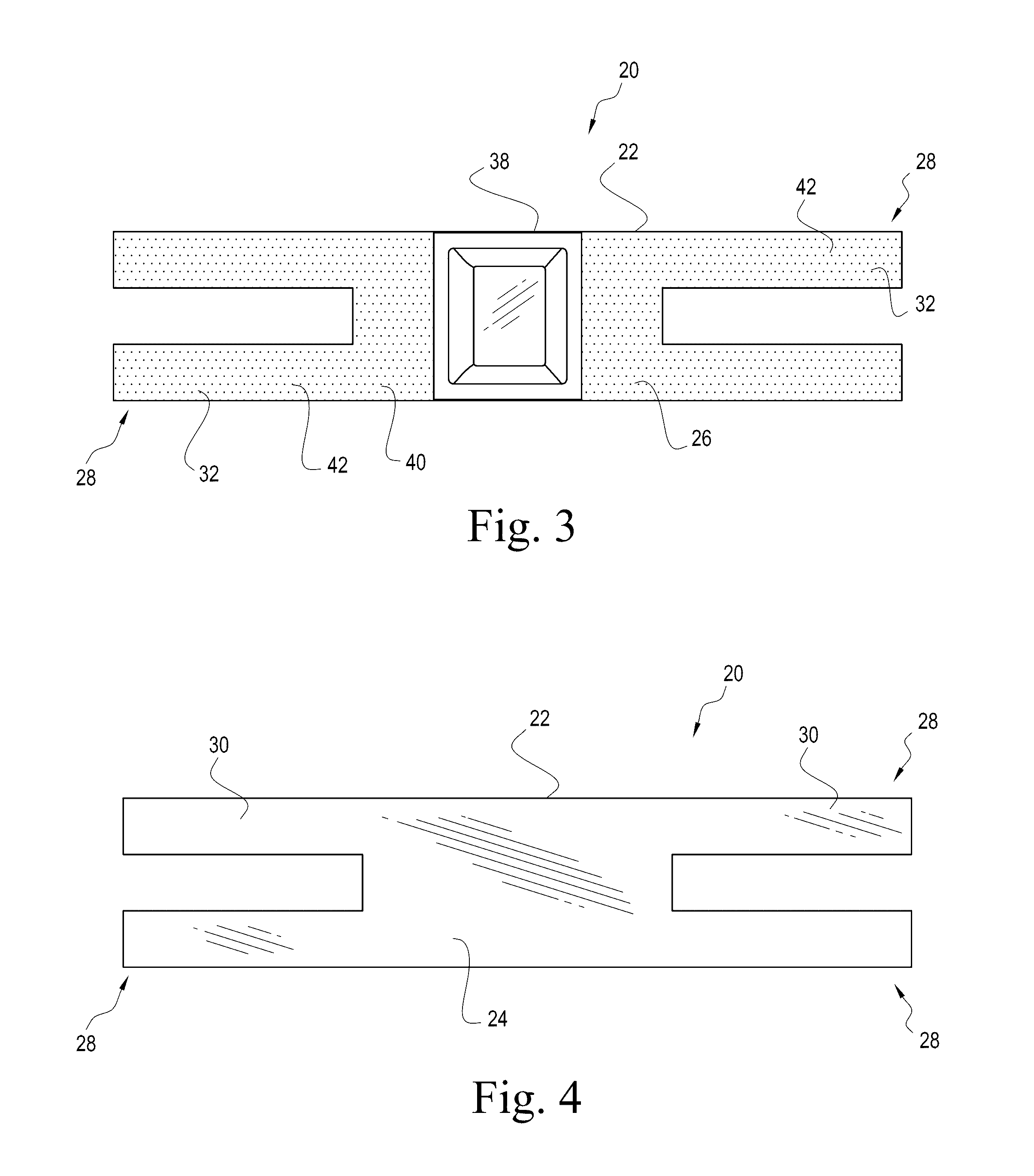
The present invention is an IV splint cover that allows for easy and comfortable IV treatments while maintaining the patient's mobility and flexibility. The cover contours to the patient's extremity where the IV is located, does not immobilize joints or cause discomfort. It also conceals the IV site, reduces the risk of occlusions and infection, and allows for easy viewing of the IV by medical professionals. The cover is securely attached to the patient's extremity and is made of a flexible material that enhances manufacturing efficiency and reduces the cost of manufacturing. The method of using the IV splint cover involves exposing the bottom portions of the main body, securing the splinting member to the IV site, and affixing the securing members to the patient's extremity.

Problems solved by technology

It can sometimes be uncomfortable when patients require medical treatment that involves an intravenous line (IV).
Although IV medical treatment is very common, and is a routine way to deliver medication, the starting of an IV is generally a process that many patients do not like, i.e., being stuck with a needle.
In some instances, an IV may come out, i.e., require reinsertion, thereby causing discomfort to the patient, and exposing the patient to possible infection.
Another issue that may arise is occlusion of the IV due to the bending of an IV tube.
Accordingly, use of the splint disclosed in the Lewis' 913 patent immobilizing a patient's extremity and can be uncomfortable for the patient.
Further, in cases where a patient may have edema, such devices do not stretch, which may cause fluid collection and clotting, which can, in turn, be problematic.
Accordingly, such device can be uncomfortable for the patient to wear on receiving IV treatments.
This device can also impede circulation by constriction and limited extremity movement.
Such a device may, however, be uncomfortable for patient, and may still inhibit flexural movement of the patient's extremity.
This device's only purpose is to prevent dislodging of the catheter, needle, etc. and does not prevent bending or kinking of the catheter, needle, etc.
Further, the device illustrated in the Bierman '001 patent may be expensive to manufacture.
This device is made of uncomfortable materials, such as metals and plastics.
Such a system depicts the very problem that needs to be addressed, i.e., immobilization of the extremities of the patient, thereby causing discomfort.
This can be an issue with patients that may suffer from dementia who may attempt to rip out an IV, or young patients that may be anxious from the sight of the IV.
In addition, such a device may still inhibit flexural movement of the patient's extremity.
This device is a clear dressing with an anchor to prevent dislodging of the catheter, needle, etc. and does not prevent bending or kinking of the catheter, needle, etc.
Further, the device may be expensive to manufacture.
Such a device may, however, be uncomfortable for the patient, and may still inhibit flexural movement of the patient's extremity.
Further, the device may be expensive to manufacture and may require specific tubing, catheters, needles, etc. so that they can matingly engage the device.
Another disadvantage of the Bierman device is that it still allows for a patient to readily view the IV site, which causes the same issues referenced above with respect to the Propp reference.
This device is used to prevent dislodging of the catheter, needle, etc. and does not prevent bending or kinking of the catheter, needle, etc.
The device in Chong, however, discloses applying a stronger adhesive to different areas of the base of a medical device, but not to the securing members when they are separate from the main body.
In addition, Chong is not an intravenous splint cover and does not allow any flexural movement of a patient's extremity when a catheter, needle, etc. is in place.
This device is an anchor and does not protect the catheter, needle, etc. or the IV site.
The device disclosed in Grubb cannot be used over an intravenous site as it will prevent the flow of fluid through the IV line and into the patient.
Cesarczyk suffers from the same defects as the '448 Grubb reference in that it is inappropriate for use in connection with the delivery of fluid through an IV.
This device, along with the device described in the Grubb reference, are inappropriate for simultaneous use with an IV and / or IV therapy.
When a patient bends his / her arm, however, or any adjacent extremity to an IV site, shifting, kinking or bending of a flexible catheter, needle, cannula, flexible tube, etc. in the vein located in a bend of the patient's extremity is not addressed by any of these devices.
Compression of the catheter, needle, cannula, flexible tube, etc. against the vessel wall is also a problem with these devices.
In addition, in the prior art, the IV site is either covered so that it is not accessible and / or viewable, without the ability to view or palpate, covered with a transparent material, or not addressed by the prior art device.
No flexibility exists in these viewing conditions.
The devices described above, and other devices that may be known in the art generally suffer from the same deficiency, i.e., the devices prevent the patient from being able to move their extremity.
Such restriction on movement also interferes with activities of daily living of the patient and immobilizes an area decreasing circulation and / or impeding blood flow.
Patients that are uncomfortable while receiving IV treatments may not respond as well to treatment as patients who are comfortable.

Method used


Image

  • Intravenous splint cover and associated methods
  • Intravenous splint cover and associated methods
  • Intravenous splint cover and associated methods

Examples


Embodiment Construction

[0042]The present invention will now be described more fully hereinafter with reference to the accompanying drawings, in which preferred embodiments of the invention are shown. This invention may, however, be embodied in many different forms and should not be construed as limited to the embodiments set forth herein. Rather, these embodiments are provided so that this disclosure will be thorough and complete, and will fully convey the scope of the invention to those skilled in the art. Like numbers refer to like elements throughout, and prime and multiple prime notations, if used, refer to similar elements in alternate embodiments.

[0043]In this detailed description of the present invention, a person skilled in the art should note that directional terms, such as “above,”“below,”“upper,”“lower,”“medial,”“center,” and other like terms are used for the convenience of the reader in reference to the drawings and the accompanying descriptions. Also, a person skilled in the art should notice...


PUM


Abstract

An intravenous splint cover may include a main body, a pair of opposing securing members, and a splinting member. The main body may be rectangular shaped and have a bottom portion and a top portion. The pair of opposing securing members may be rectangular shaped and be connected to and extend outwardly from the main body and have a bottom portion and a top portion. The splinting member may be rectangular shaped and be carried by the bottom portion of the main body and extend outwardly from the main body to create an elevated portion of the main body. The bottom portions of the pair of opposing securing members may have an adhesive material applied thereto. The bottom portion of the main body that does not carry the splinting member may have an adhesive material applied thereto.

Description

RELATED APPLICATIONS[0001]This application is a continuation-in-part and claims the benefit under 35 U.S.C. §120 of U.S. patent application Ser. No. 13 / 367,498 filed on Feb. 7, 2012 and titled Intravenous Splint Cover and Associated Methods (Attorney Docket No. 111.4862), the entire contents of which are incorporated herein by reference herein in its entirety except to the extent disclosure therein is inconsistent with disclosure herein.FIELD OF THE INVENTION[0002]The present invention relates to the medical field and, more specifically, to the field of intravenous splint covers and associated methods.BACKGROUND OF THE INVENTION[0003]It can sometimes be uncomfortable when patients require medical treatment that involves an intravenous line (IV). Although IV medical treatment is very common, and is a routine way to deliver medication, the starting of an IV is generally a process that many patients do not like, i.e., being stuck with a needle. In some instances, an IV may come out, i....

Claims


Application Information

Patent Timeline
IPC IPC(8): A61M25/02A61F5/058A61F13/10
CPCA61M25/02A61F13/101A61M2025/026A61F2013/00272A61F2013/0028A61F5/058A61F15/008A61F13/0273A61F2013/00412A61M2025/0213A61M2025/0266
Inventor WILBORN, MARIE-ANDREA I.FONGEMIE, MARIE THERESE R.
Owner WILBORN MARIE ANDREA I
Learn More