
Apparatus and method for precision thermal processing of a body

Inactive Publication Date: 2016-10-06
FRACTURELAB
View PDF0 Cites 41 Cited by
  • Summary
  • Abstract
  • Description
  • Claims
  • Application Information

AI Technical Summary

Benefits of technology

This patent describes an apparatus for thermal processing of materials, such as turbine blades, using laser technology. The apparatus can create high-quality parts by inducing controlled dendrite growth, which can form in the material during processing. The apparatus can have a fixed or adaptive optical properties, and can be used in open or closed loop processes. The system can also measure and control the surface temperature within the processing spot, ensuring stable processing results. Overall, this patent provides a more effective way to manufacture and repair single-crystal parts using laser technology.

Problems solved by technology

As mentioned earlier, recent prior art, even when performed by highly skilled practitioner, has been unable to maintain the level of thermal control necessary to additively manufacture quality multi-layer single-crystal nickel superalloy parts or repairs, and even single-layer deposits do not achieve the desired level of quality for repairs.
Commercially available SLM devices available at this writing are currently limited to relatively low (albeit useful) optical power operation, but are expected to increase in capability over time as screens with larger active area are produced, and / or the permissible flux is increased.

Method used


Image

  • Apparatus and method for precision thermal processing of a body
  • Apparatus and method for precision thermal processing of a body
  • Apparatus and method for precision thermal processing of a body

Examples


Embodiment Construction

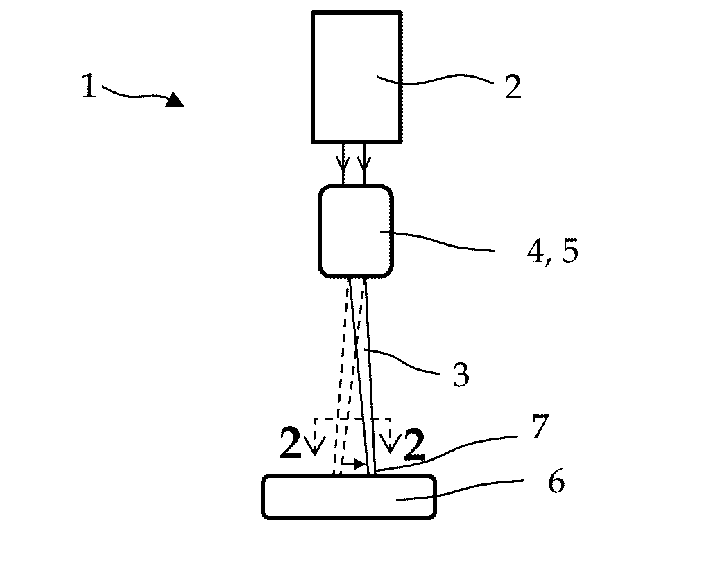
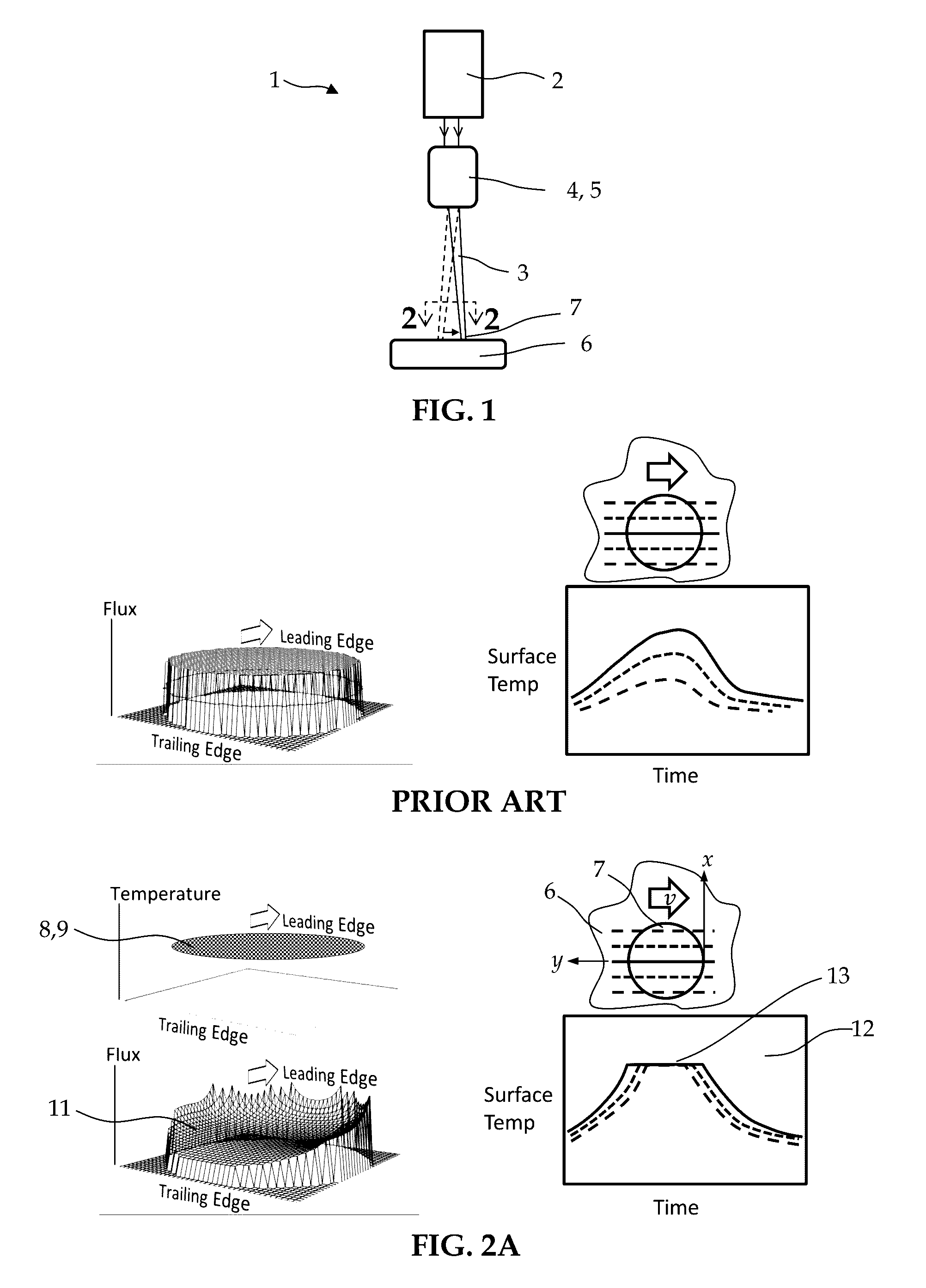
[0063]FIG. 1, shows a schematic representation of an apparatus 1 for precision thermal processing of a body 6. The exemplary embodiment includes an energy beam 3 emanating from an energy beam source 2, a means 4 to scan the beam 3 across the surface of the body 6, thereby creating heat input through a moving spot 7 on the surface of the body 6, and means 5 to condition the spot shape and flux profile. The means 4 to scan and the means 5 to condition the spot 7 are sometimes integrated as illustrated here, or may be embodied as separate and distinct means as will be described hereafter. While not shown, a computer or microprocessor is often required to operate many of the devices incorporated into this or other embodiments to be shown hereafter.

[0064]For the purposes of this exemplary embodiment, the beam source 2 and scanning system 4 may be selected without restriction from technology known to one skilled in the art. For example the beam source 2 may be a laser or an electron beam ...


PUM

PropertyMeasurementUnit
Temperatureaaaaaaaaaa
Lengthaaaaaaaaaa
Diameteraaaaaaaaaa

Abstract

The invention pertains to apparatus and method for precision thermal processing of a body. An energy beam emanating from an energy beam source is scanned across the surface of the body, creating heat input through a moving spot on the surface of said body. By means described herein to condition the spot shape and flux profile, the flux profile within the spot is configured to approximate a thermal solution obtained by solving a boundary condition of the third kind imposed upon the moving spot associated with the beam as it is scanned across the body. In this manner a predetermined surface temperature profile is imposed on the surface of the body within a moving, locally heated spot of predetermined shape and size.Potential uses include any application which would benefit from the ability to apply a prescribed uniform or variable thermal process to the surface of a body, thus including but not limited to thermal processing of inorganic materials, such as metals and ceramics, and thermal processing of polymeric or organic materials or tissues. Exemplary desired outcomes range from an improvement of surface properties, such as hardness or wear resistance, to the fabrication of a component through an additive manufacturing process.

Description

CROSS-REFERENCE TO RELATED APPLICATIONS[0001]Not Applicable.BACKGROUND OF THE INVENTION[0002]1. Field of the Invention[0003]The invention pertains to an apparatus and method for precision thermal processing of a body with an energy beam such as a laser or an electron beam. Potential uses include any application which would benefit from the ability to apply a prescribed uniform or variable thermal process to the surface of a body, thus including but not limited to thermal processing of inorganic materials, such as metals and ceramics, and thermal processing of polymeric or organic materials or tissues. Exemplary desired outcomes range from an improvement of surface properties, such as hardness or wear resistance, to the fabrication of a component through an additive manufacturing process. While prior art can already perform many of these tasks after a sort, the proposed technology is distinguished by a degree of precision with which the thermal process can be carried out, thus render...

Claims


Application Information

Patent Timeline
IPC IPC(8): B23K26/064B23K26/073G02B27/42B23K26/342B23K15/00B23K15/02B23K26/06B23K26/082
CPCB23K26/064B23K26/0626B23K26/0732B23K26/082B33Y30/00B23K15/0086B23K15/02G02B27/4233B33Y10/00B23K26/342G02B26/101B22F3/24B23K26/034B23K26/0648B23K26/0823B23K26/0876B22F2998/10B33Y40/00B23K26/144B23K2101/001B23K2103/26Y02P10/25B22F10/25B22F2003/248B22F10/28
Inventor PETTIT, RICHARD G.MAROTTA, MICHAEL D.
Owner FRACTURELAB
Learn More