
Control circuits for dynamically biased avalanche photodiodes

Inactive Publication Date: 2016-09-29
DYNAMIC PHOTONICS INC
View PDF1 Cites 4 Cited by
  • Summary
  • Abstract
  • Description
  • Claims
  • Application Information

AI Technical Summary

Benefits of technology

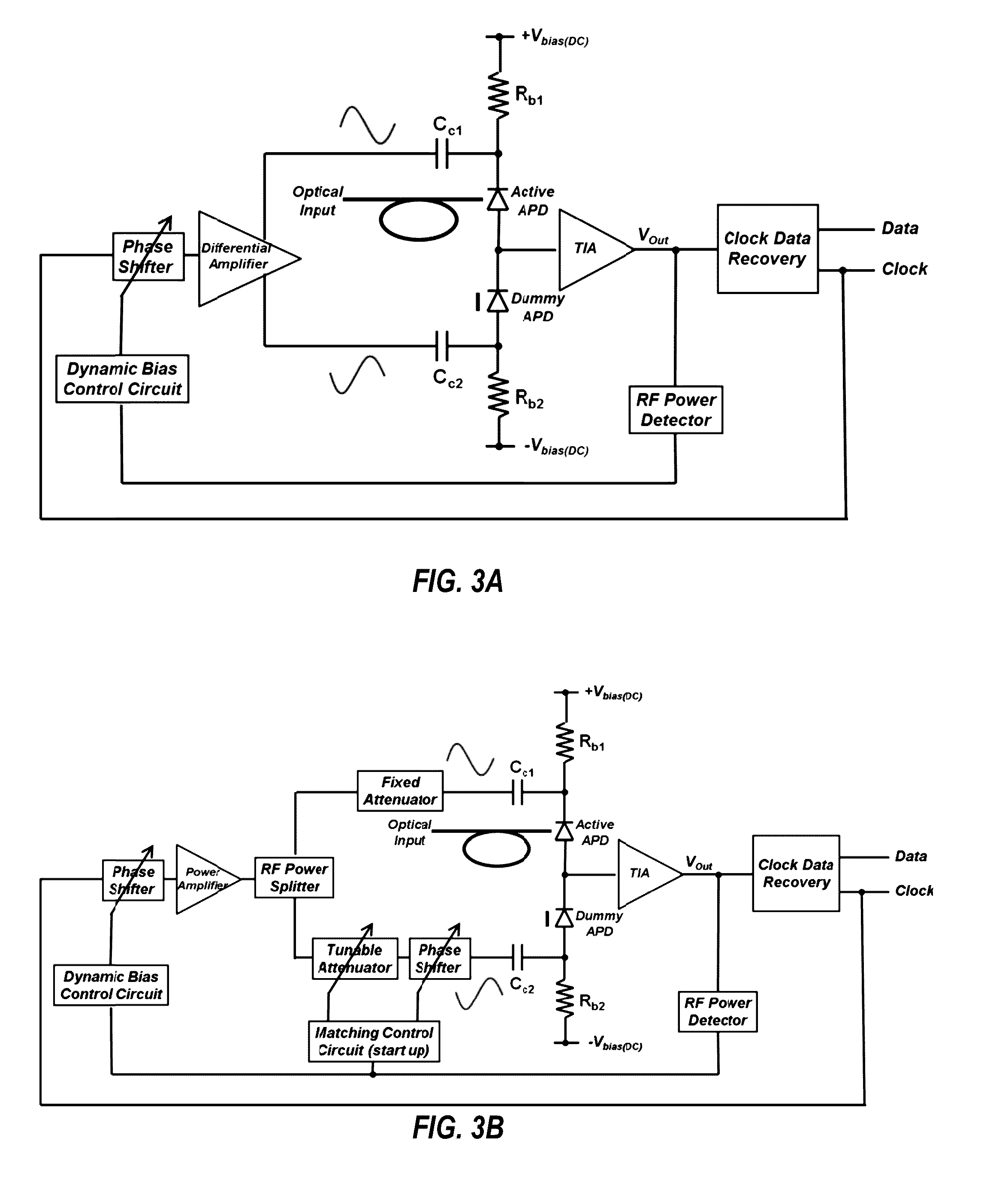
The present invention is a method and apparatus for maximizing the output signal of a dynamically biased avalanche photodiode (APD) by amplifying the output signal using a transimpedance amplifier, measuring the amplified output, and automatically varying the phase of the AC signal used to dynamically bias the APD until a maximum of the amplified output is achieved. The method may also involve splitting the AC signal in two and canceling out the signal to remove noise, and filtering the amplified output to perform functions such as temporal averaging and accentuating correction of output components. The technical effects of the invention are improved RF power output and increased efficiency of the APD in generating high-quality signals.

Problems solved by technology

However, the APD's internal gain comes at the cost of the avalanche-buildup time, the time it takes for the chain of all impact ionizations to terminate every time a photon-generated carrier triggers an avalanche of impact ionizations.
The relatively long buildup time often limits the APD's gain-bandwidth product (GBP) and can lead to inter-symbol interference (ISI) when the APD is operated at gains of interest (>10) in high-speed optical receivers.
Thus current APDs are not able to meet the requirements for high bit-rate telecom systems.
Currently there are no commercially available telecommunications APDs that can operate at the rate of 40 gigabits per second (Gbps).
However, they suffer from the tradeoff between responsivity (which improves with the waveguide length) and speed (which decreases as the device capacitance increases with the waveguide length).
In addition, they have very tight optical tolerance requirements due to the narrow waveguide.
While Si—Ge APDs have shown promise in this direction, their overall effectiveness has not been demonstrated due to their low responsivity and high dark currents.
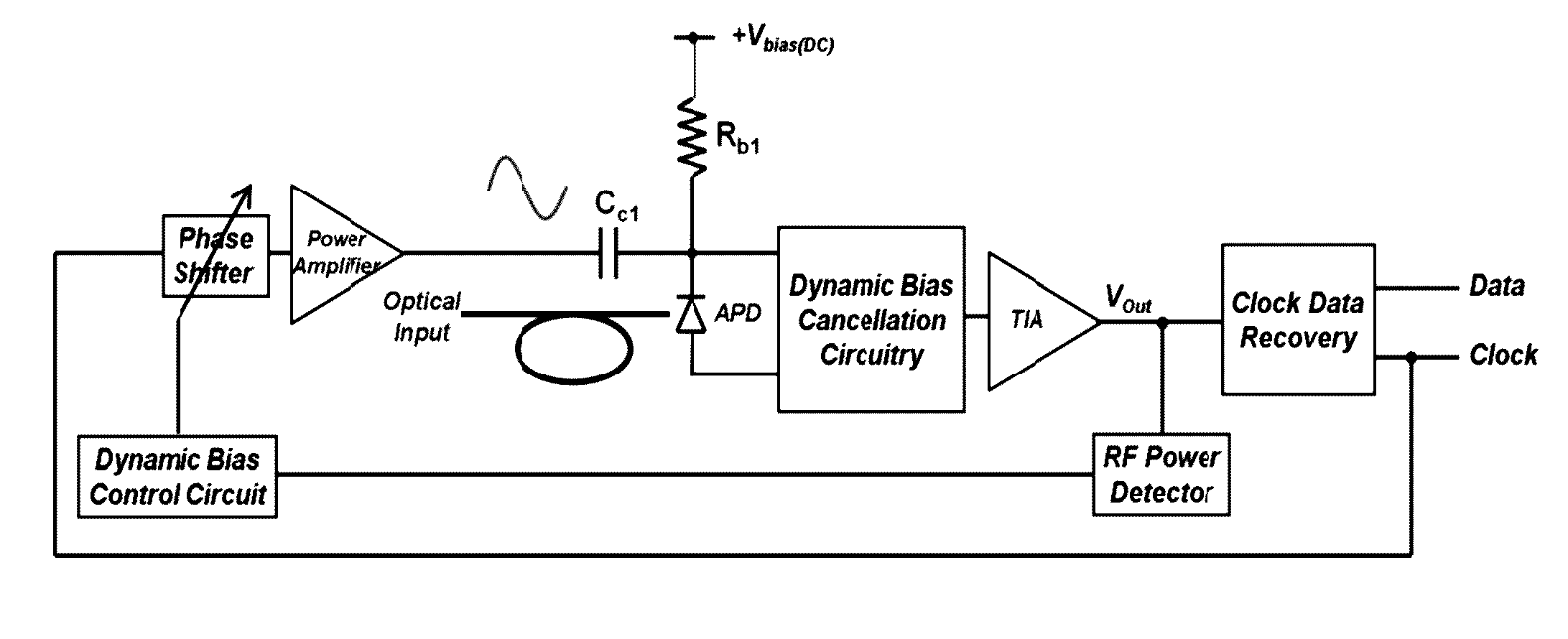
One difficulty of implementing dynamic biasing APDs is their parasitic capacitance, which causes the dynamic-bias signal to be injected into the optical current generated by the APD (FIG. 1).
At high frequencies the injected bias current, which is unwanted at the output signal, can be orders of magnitude larger than the optical current (signal), and overwhelms it completely.
Currently there is no automatic phase-tuning circuit available that can address the state problem.

Method used


Image

  • Control circuits for dynamically biased avalanche photodiodes
  • Control circuits for dynamically biased avalanche photodiodes
  • Control circuits for dynamically biased avalanche photodiodes

Examples


Embodiment Construction

[0023]Embodiments of the present invention reduce or eliminate current injection in dynamically biased APDs, and also make the dynamic biasing approach robust in the face of environment changes of the circuit such as changes in temperature, aging of components, etc. Embodiments of the present invention preferably use a control / feedback signal obtained from the output to implement a phase-tuning circuit in order to yield the maximum signal strength. As shown in FIG. 2, a radio frequency (RF) power detector is preferably used to measure the RMS value of the RF signal generated by the trans-impedance amplifier (TIA) and use it to tune the phase of the dynamic bias in order to electronically optimize the RF output power. The dynamic bias control circuit adjusts the phase of the AC dynamic bias via the phase shifter while measuring the output from the RF power detector until it detects the maximum of the output power. Since the dynamics of PLL inside the clock-data recovery circuit are i...


PUM


Abstract

Method and apparatus for maximizing the output of a dynamically biased avalanche photodiode (APD). The output of the APD is amplified. A feedback loop comprising a phase shifter measures the RF power of the amplified output and adjusts the phase of the AC signal which is used to dynamically bias the APD until the output power is maximized. The AC signal is also split into out of phase signals, thereby substantially canceling out the bias current injected into the APD output, leaving only the desired amplified optical output signal. The monitoring and tuning of the AC dynamic bias can eliminate phase drift over time, as well as other non-ideal effects that can occur, such as those due to temperature changes or device aging effects.

Description

CROSS-REFERENCE TO RELATED APPLICATIONS[0001]This application claims priority to and the benefit of filing of U.S. Provisional Patent Application Ser. No. 62 / 138,183, entitled “Control Circuits for Dynamically Biased Avalanche Photodiodes”, filed on Mar. 25, 2015, the specification of which is incorporated herein by reference.BACKGROUND OF THE INVENTION[0002]1. Field of the Invention (Technical Field)[0003]The present invention relates to circuits and methods for the automatic control and tuning of the dynamic bias phase used for avalanche photodiodes without altering the incoming data.[0004]2. Background of the Invention[0005]Note that the following discussion may refer to a number of publications and references. Discussion of such publications herein is given for more complete background of the scientific principles and is not to be construed as an admission that such publications are prior art for patentability determination purposes.[0006]Avalanche photodiodes (APDs) are the pho...

Claims


Application Information

Patent Timeline
IPC IPC(8): H01L31/02H01L31/107H01L31/0304
CPCH01L31/02027H01L31/107H01L31/0304Y02E10/544
Inventor ZARKESH-HA, PAYMANHAYAT, MAJEED M.EFROYMSON, ROBERT
Owner DYNAMIC PHOTONICS INC
Learn More