
Characterizing tropospheric boundary layer thermodynamic and refractivity profiles utilizing multiband infrared observations

a thermodynamic and refractive profile technology, applied in the field of passive characterization of atmospheric characteristics, can solve the problems of loss of the ability to make visual, radio, and/or radar contact, difficult deployment of systems using infrared (ir), visible and ultraviolet, radio/radar waveband, etc., and achieves easy operation, rapid steering, and low cost of deployment and operation.

Inactive Publication Date: 2016-09-22
SOLHEIM FREDRICK S
View PDF10 Cites 9 Cited by
  • Summary
  • Abstract
  • Description
  • Claims
  • Application Information

AI Technical Summary

Benefits of technology

The patent describes an invention that provides a device and method for measuring the temperature, pressure, water vapor, and refractivity of the atmosphere using infrared imaging. This device is fully passive, all-weather, and can operate both day and night. It is designed to characterize the boundaries of the atmosphere and determine its effect on electromagnetic propagation. Additionally, the device is highly adaptable, portable, and can be easily operated by a single operator or automation. The invention can be used for both continuous operation and in high sea states. Overall, the technical effects of the invention include accurate and fast measurement of meteorological parameters, high adaptability, and the ability to operate in various sea states. Its application can be unobtrusive and covert, and it can provide valuable information on air quality and laminar or turbulent air flow.

Problems solved by technology

Inaccurate characterization of tropospheric meteorological parameters, such as the vertical profiles and structure of temperature, pressure, water vapor and refractivity, and of electromagnetic propagation, particularly over water, has long resulted in difficulty deploying systems using infrared (IR), visible and ultraviolet, and radio / RADAR wavebands.
Since the effects in each differ due to the spectral real (phase delay) and imaginary (absorption) components of refractivity characteristics of water vapor and the dry constituency of the troposphere, such difficulties have been especially acute for oceangoing operations such as naval needs for passive continuous characterization of the evaporation layer in the entire optical region and in the radio / radar regions of the electromagnetic spectrum.
Moreover, certain refractivity gradients can cause blind segments at different elevations above the horizon with resulting loss of the ability to make visual, radio, and / or radar contact.
This phenomenon can blind vessels to threats in their environment, make aircraft recovery difficult, or (undesirably) make them visible in various wavebands at long ranges.
This ducting can also occur in arctic regions, interfering with radio communications.
But radiosondes are difficult to manage from ships, contain a radio transmitter and are therefore not passive, have long rise times, and define a single trajectory in space.
All of these current methods suffer from lack of accuracy, timeliness and covertness.
Furthermore, there may be azimuthal gradients in the refractivity effects that a radiosonde or models would not define.
More generally, these inaccurate characterizations debilitate accurate meteorological analysis.
These radiosondes use large amounts of helium at each launch thus adding to depletion of limited helium reserves.
However, none of these methods is passive, and are therefore not suitable for unobtrusive and / covert uses (such military application, for example).
All are costly, and have intrusive environmental impacts, are cumbersome and thus not portable, require excessive personnel to deploy and operate, and typically provide only local or temporally and spatially sparse data.
Laminar flow enables optimum wind energy harvesting, whereas turbulent flow can damage wind turbines and cause their failure.

Method used


Image

  • Characterizing tropospheric boundary layer thermodynamic and refractivity profiles utilizing multiband infrared observations
  • Characterizing tropospheric boundary layer thermodynamic and refractivity profiles utilizing multiband infrared observations
  • Characterizing tropospheric boundary layer thermodynamic and refractivity profiles utilizing multiband infrared observations

Examples


Embodiment Construction

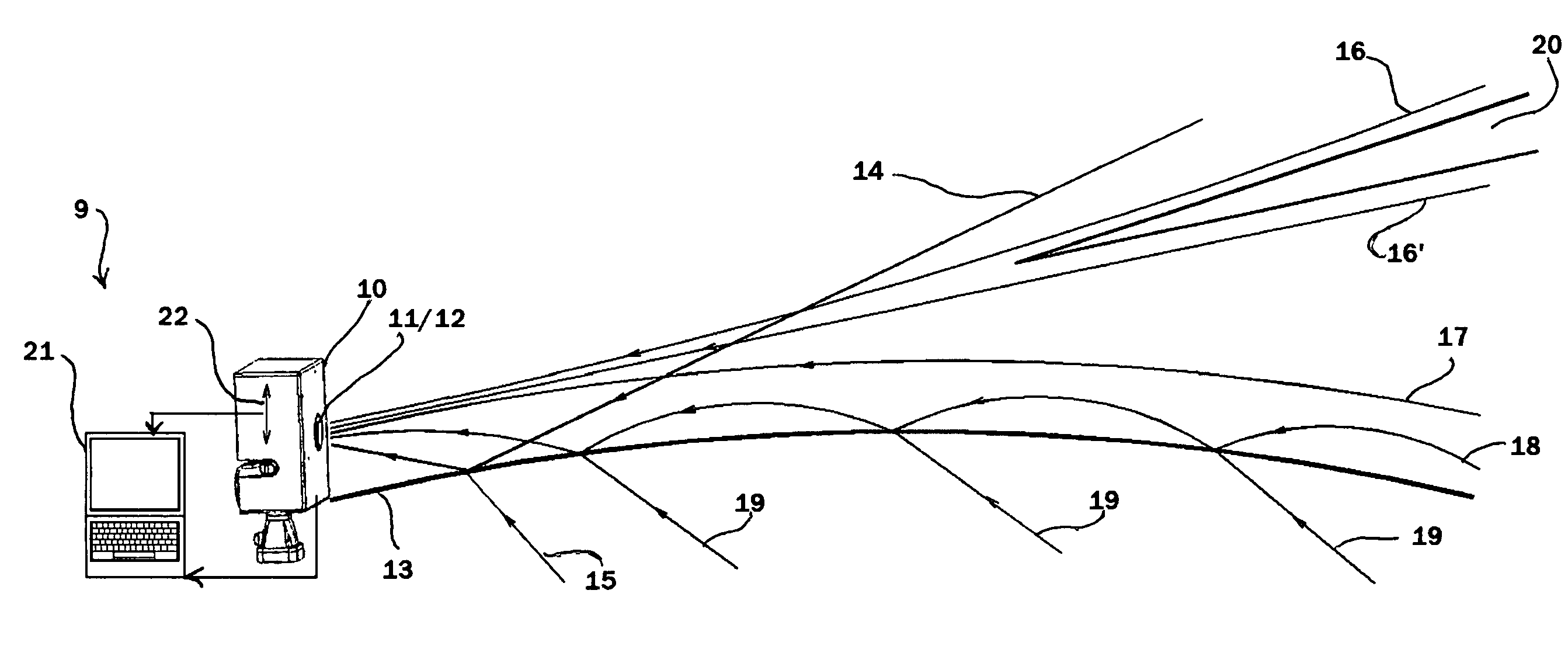
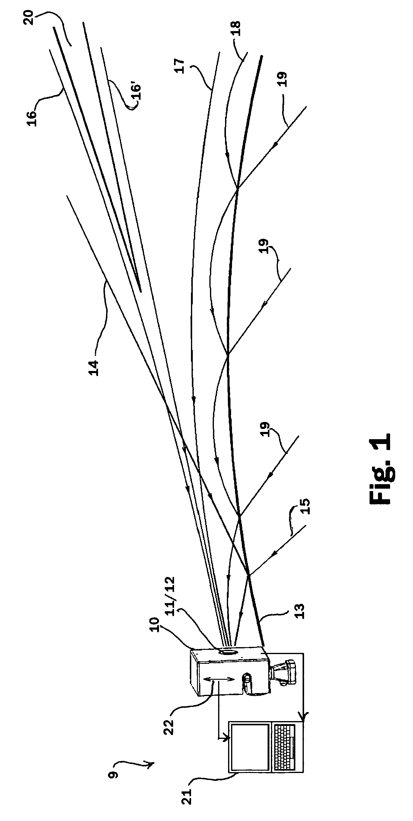
[0041]FIG. 1 in part illustrates effects of various refractive gradients upon electromagnetic propagation over water. Observed in infrared spatial observations (in this case infrared images but which could alternatively be vertical gradients) of the vicinity of the horizon under such conditions are horizontal layers (or quasihorizontal layers in the presence of horizontal gradients) of optical paths beginning upward from below the optical horizon and progressing upward (with similar effects upon propagation paths in the other optical and radio / RADAR bands). The electromagnetic flux from these layers may originate from over long distances over the ocean, may originate from the ocean, may make multiple reflections off the ocean surface and the under-side of the ducting layer, or may originate from above the horizon in the cold sky. They therefore manifest as layers of differing temperatures in infrared images.

[0042]FIG. 1 (illustrating a trapping of electromagnetic radiation in the du...


PUM

PropertyMeasurementUnit
heightsaaaaaaaaaa
temperatureaaaaaaaaaa
pressureaaaaaaaaaa

Abstract

Apparatus and methods are disclosed utilizing selected infrared spectrum spatial observations to determine selected profiles of interest. A correlative system is constructed and installed at a processor. Thermal profiles and structure in the wavebands of interest are extracted from observed infrared spectrum multiband observations received for processing at the processor by the correlative system. The output provides the selected profiles of interest in the wavebands of interest. The apparatus includes an infrared receiver system and means for controlling and measuring angular displacement of received emissions relative to a horizon. The processor converts received emission into equivalent blackbody temperatures across the observations and correlates structure and vertical distribution of the temperatures.

Description

FIELD OF THE INVENTION[0001]This invention relates to passively characterizing atmospheric characteristics, and, more particularly, relates to methods and apparatus for such characterization using infrared spectrum spatial observations.BACKGROUND OF THE INVENTION[0002]Inaccurate characterization of tropospheric meteorological parameters, such as the vertical profiles and structure of temperature, pressure, water vapor and refractivity, and of electromagnetic propagation, particularly over water, has long resulted in difficulty deploying systems using infrared (IR), visible and ultraviolet, and radio / RADAR wavebands. Since the effects in each differ due to the spectral real (phase delay) and imaginary (absorption) components of refractivity characteristics of water vapor and the dry constituency of the troposphere, such difficulties have been especially acute for oceangoing operations such as naval needs for passive continuous characterization of the evaporation layer in the entire o...

Claims


Application Information

Patent Timeline
Patent Type & Authority Applications(United States)
IPC IPC(8): G01N21/41G01W1/00
CPCG01N21/41G01N2201/12G01W1/00
Inventor SOLHEIM, FREDRICK S.
Owner SOLHEIM FREDRICK S
Learn More