Drive torque distribution method, device and automobile
A driving torque and front-drive technology, applied in the automotive field, can solve problems such as vehicle loss of stability, and achieve the effect of avoiding vehicle flicking or sideslip, ensuring operation stability and safety performance, and ensuring safety performance
- Summary
- Abstract
- Description
- Claims
- Application Information
AI Technical Summary
Problems solved by technology
Method used
Image
Examples
Embodiment 1
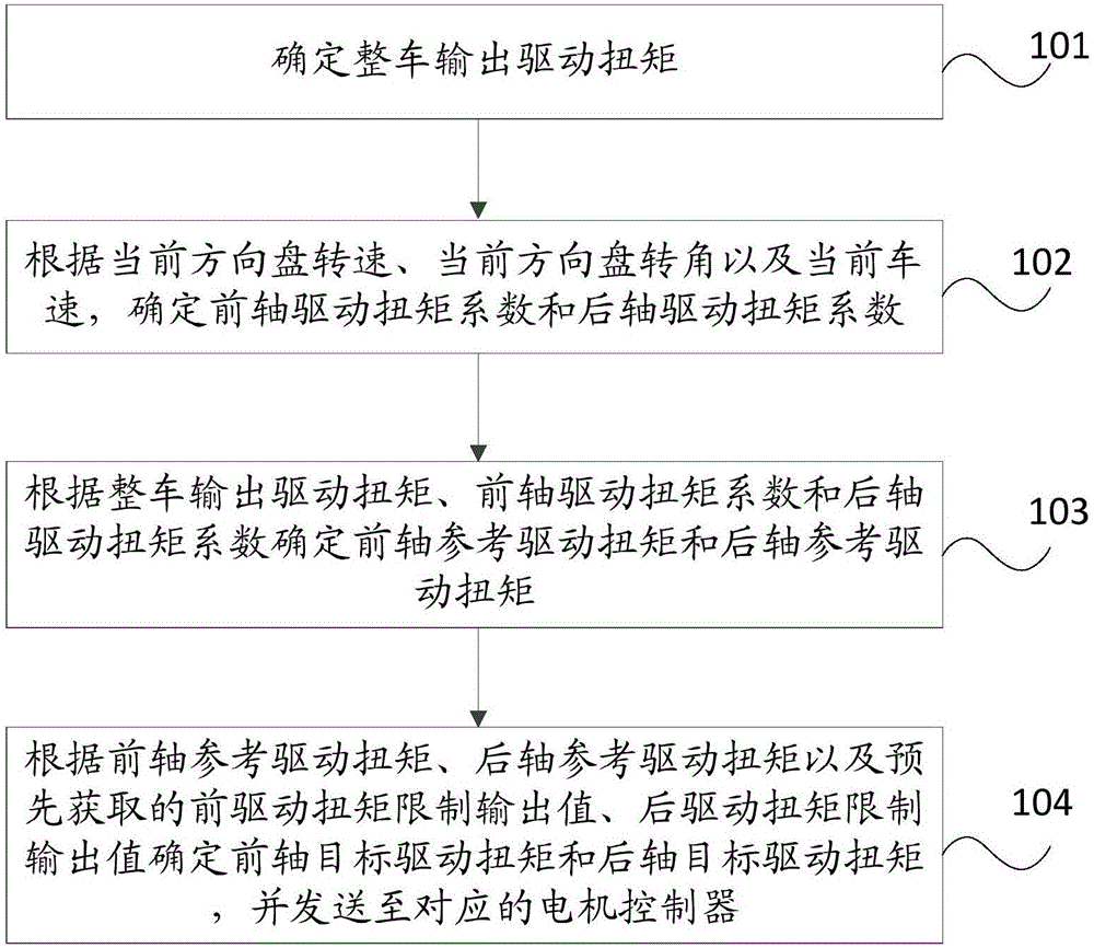
[0071] Such as figure 1 As shown, the driving torque distribution method provided by Embodiment 1 of the present invention includes:
[0072] Step 101, determine the output drive torque of the vehicle.
[0073] The present invention is applied to a vehicle controller. Firstly, the vehicle controller needs to determine a required output drive torque of the vehicle according to the pedals. The pedal here includes a brake pedal and an accelerator pedal. When it is detected that the switch signal of the brake pedal is on, it is determined that the brake pedal signal is valid, and the first output drive torque corresponding to the pedal is zero at this time. When the switch signal is off, the first output driving torque is calculated according to the opening degree signal of the accelerator pedal. At the same time, the current effective power of the power battery needs to be obtained, and the second output driving torque supported by the power battery is determined according to t...
Embodiment 2
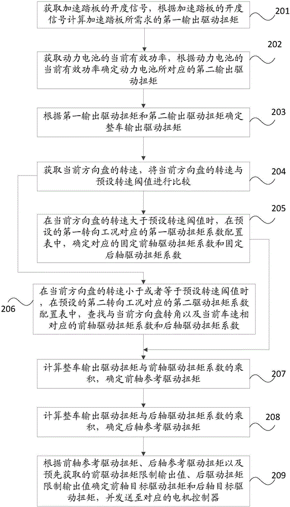
[0086] Such as figure 2 As shown, the driving torque distribution method provided by Embodiment 2 of the present invention includes:
[0087] Step 201 , acquiring an accelerator pedal opening signal, and calculating a first output driving torque required by the accelerator pedal according to the accelerator pedal opening signal.
[0088] First, the vehicle controller needs to determine the first output driving torque according to the pedal. The pedal here includes a brake pedal and an accelerator pedal. When it is detected that the switch signal of the brake pedal is on, it is determined that the brake pedal signal is valid, and the first output drive torque corresponding to the pedal is zero at this time. When the switch signal is off, the first output driving torque is calculated according to the opening degree signal of the accelerator pedal.
[0089] Step 202. Obtain the current effective power of the power battery, and determine the second output driving torque corresp...
Embodiment 3
[0130] Such as Image 6 As shown, the drive torque distribution system architecture provided by Embodiment 3 of the present invention includes:
[0131] The vehicle controller 600, the brake pedal 601 and the accelerator pedal 602 electrically connected to the input end of the vehicle controller 600;
[0132] The brake anti-lock braking system 603, the steering wheel angle sensor 604 and the battery management system 605 connected to the input end of the vehicle controller 600 through the CAN bus; and
[0133] A front axle motor controller 606 and a rear axle motor controller 607 connected to the output end of the vehicle controller 600 through the CAN bus, wherein the front axle motor controller 606 is connected to the front drive motor 608, and the rear axle motor controller 607 is connected to the rear axle motor controller 607. The drive motor 609 is connected.
[0134] Specifically, when the vehicle controller 600 detects that the switch signal of the brake pedal 601 is...
PUM
 Abstract
Description
Claims
Application Information
 - R&D Engineer
- R&D Manager
- IP Professional
- Industry Leading Data Capabilities
- Powerful AI technology
- Patent DNA Extraction
Browse by: Latest US Patents, China's latest patents, Technical Efficacy Thesaurus, Application Domain, Technology Topic, Popular Technical Reports.
© 2024 PatSnap. All rights reserved.Legal|Privacy policy|Modern Slavery Act Transparency Statement|Sitemap|About US| Contact US: help@patsnap.com


