
Electrolytic Copper Foil, Electric Component and Battery Including the Same

a technology of electric components and copper foils, applied in the direction of printed circuit aspects, cell components, metallic pattern materials, etc., can solve the problems of reduced adhesion of rolling copper foils to active materials, high manufacturing costs, and difficult manufacturing of wide width rolling copper foils

Active Publication Date: 2016-09-08
ILJIN MATERIALS CO LTD
View PDF6 Cites 20 Cited by
  • Summary
  • Abstract
  • Description
  • Claims
  • Application Information

AI Technical Summary

Benefits of technology

The present invention provides an electrolytic copper foil with certain characteristics such as small pore size, high glossiness, and high tensile strength. The foil also has good elongation before and after heat treatment, as well as a unique corner curl angle and thickness. The use of this foil in batteries and electric components is also described. In summary, the technical effects of this invention are to provide an improved electrolytic copper foil with improved properties that can be used in a variety of applications.

Problems solved by technology

As the copper foil, a rolling copper foil which is manufactured by rolling working has been mainly used, but manufacturing cost is expensive and it is difficult to manufacture a copper foil having a wide width.
Further, the rolling copper foil has reduced adhesion to an active material due to pollution of lubricating oil since the lubricating oil needs to be used at the time of the rolling working, and thus charging and discharging cycle characteristics of the battery may be degraded.
In particular, when a line width of the wiring pattern formed by the etching is narrow, the wiring may be short-circuited.
However, a thickness of the copper foil is limited due to a thin copper foil and thus the copper foil has weak mechanical strength, such that the occurrence frequency of defects such as wrinkle and bending is increased at the time of manufacturing the printed wiring board.

Method used


Image

  • Electrolytic Copper Foil, Electric Component and Battery Including the Same
  • Electrolytic Copper Foil, Electric Component and Battery Including the Same
  • Electrolytic Copper Foil, Electric Component and Battery Including the Same

Examples


example 1

[0091]To manufacture the electrolytic copper foil by electrolysis, a 3 L of electrolytic bath system which may be circulated at 20 L / min was used and the temperature of the copper electrolyte was constantly maintained at 45° C. The anode used a pole plate of a dimentionally stable electrode (DSE) which has a thickness of 5 mm and a size of 10×10 cm2 and the cathode used a titanium pole plate which has the same size and thickness as the anode.

[0092]To smoothly move the Cu2+ ion, plating was performed in a current density of 35 A / dm2 and the electrolytic copper foil having a thickness of 18 μm was manufactured.

[0093]A basic composition of the copper electrolyte is as follows.[0094]CuSO4.5H2O: 250˜400 g / L[0095]H2SO4: 80˜150 g / L

[0096]The copper electrolyte was added with the chlorine ion and the additives and the composition of the additives and the chlorine ion which are added was shown in the following Table 1. In the following Table 1, ppm is the same as mg / L.

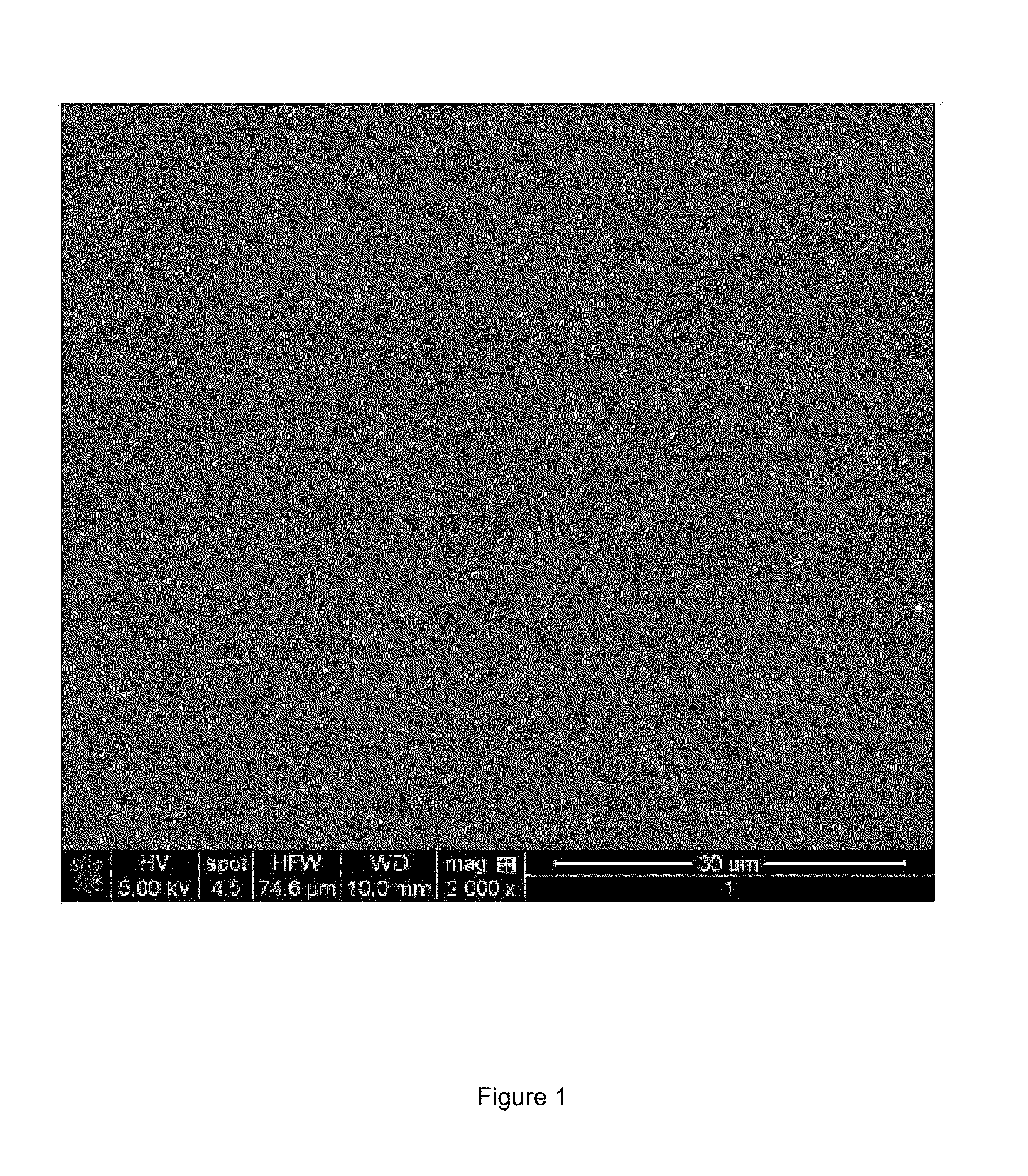
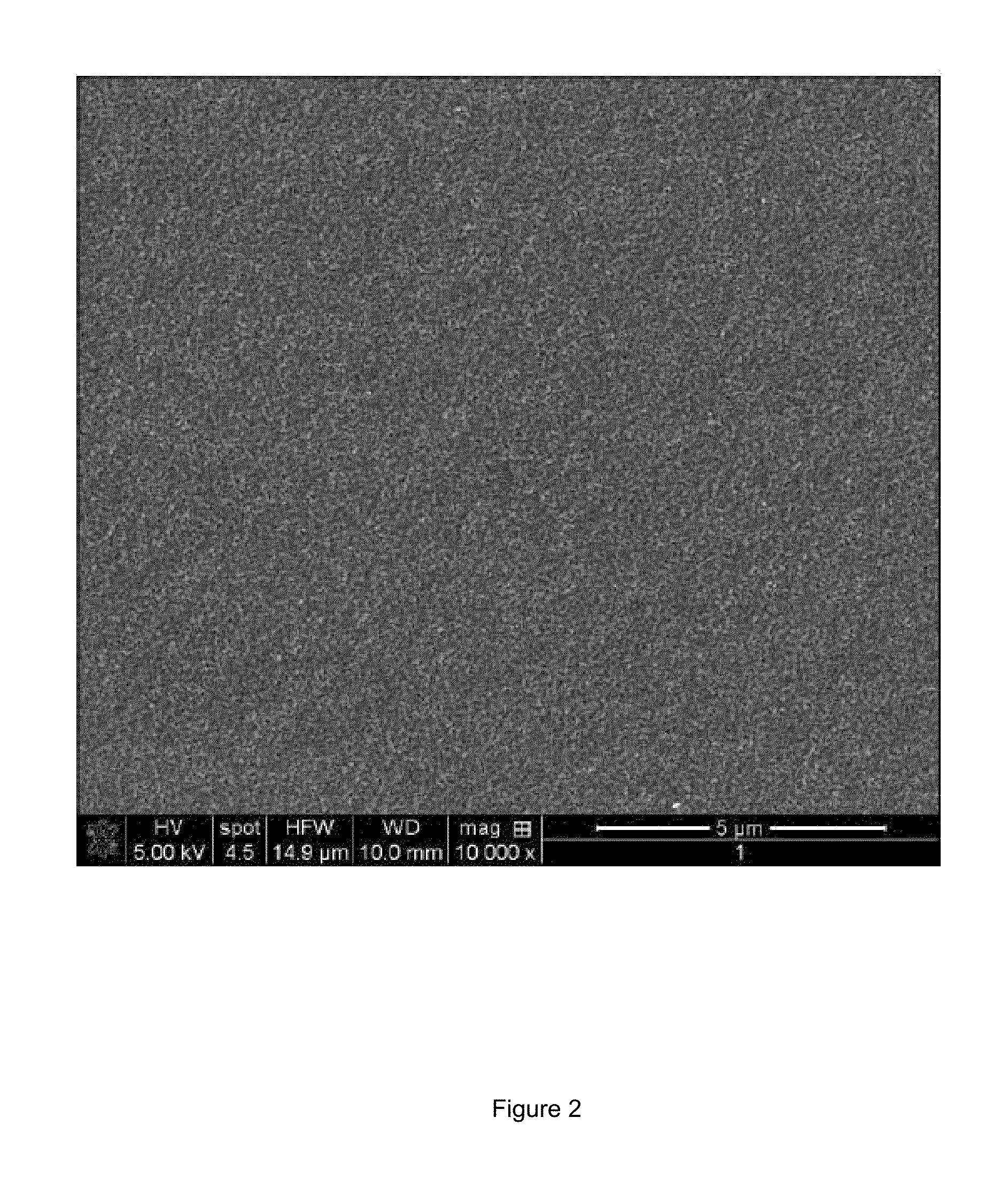
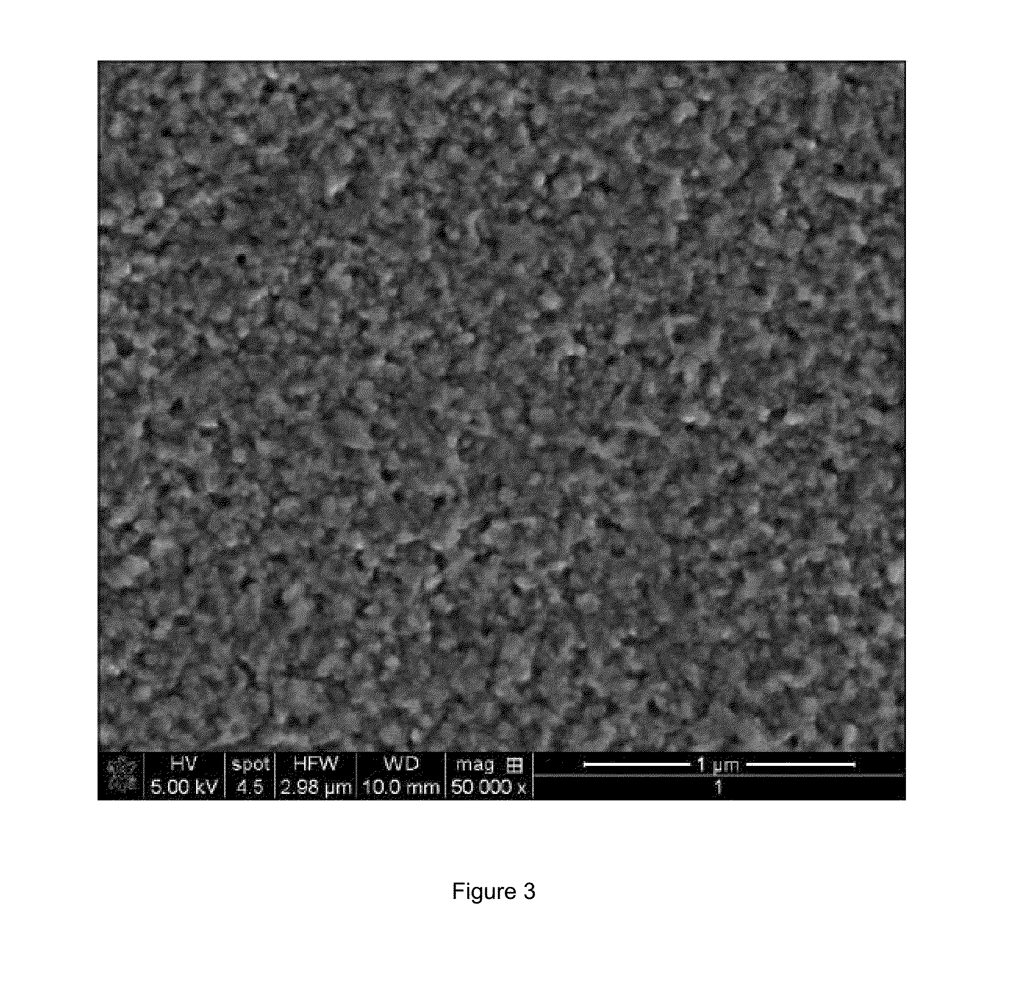
[0097]A photograph of a ...


PUM

PropertyMeasurementUnit
Temperatureaaaaaaaaaa
Fractionaaaaaaaaaa
Fractionaaaaaaaaaa

Abstract

Disclosed herein is an electrolytic copper foil in which an average diameter of a pore which is a region between surface elements protruding from a matte side is 1 mm to 100 nm. The electrolytic copper foil has high elongation while maintaining low roughness and high strength and thus may be used in a current collector of a medium-large size lithium ion secondary battery and a semiconductor packaging substrate, and the like, for tape automated bonding (TAB) which is used in a tape carrier package (TCP).

Description

CROSS-REFERENCE TO RELATED APPLICATION(S)[0001]This application claims priority to Korean Patent Application No. 10-2013-0122071, filed on Oct. 14, 2013, the disclosure(s) of which is incorporated herein by reference in its (their) entirety.BACKGROUND OF THE INVENTION[0002]1. Field of the Invention[0003]Exemplary embodiments of the present invention relate to an electrolytic copper foil, an electric component and a battery including the same, and more particularly, to a low-roughness, high-strength, and high-elongation electrolytic copper foil which has high tensile strength and elongation even after being subjected to high-temperature heat treatment.[0004]2. Description of the Related Art[0005]As a current collector of a secondary battery, a copper foil is generally used. As the copper foil, a rolling copper foil which is manufactured by rolling working has been mainly used, but manufacturing cost is expensive and it is difficult to manufacture a copper foil having a wide width. Fu...

Claims


Application Information

Patent Timeline
IPC IPC(8): H01M4/66H05K1/09C25D7/06
CPCH01M4/661H05K2201/0355H05K1/09C25D7/0614C25D1/04C25D3/38H01M10/052Y02E60/10
Inventor LEE, SUN HYOUNGJO, TAE JINPARK, SEUL KISONG, KI DEOK
Owner ILJIN MATERIALS CO LTD
Learn More