
Ultra-lightweight clamping device

a clamping device, ultra-light weight technology, applied in the direction of work holders, chucks, manufacturing tools, etc., can solve the problems of limiting the processing or transportation of sensitive workpieces, high weight, and high wear on the clamping device, so as to reduce wear, simplify maintenance, and increase the clamping force of the gripper

Inactive Publication Date: 2016-09-08
ROHM GMBH
View PDF9 Cites 3 Cited by
  • Summary
  • Abstract
  • Description
  • Claims
  • Application Information

AI Technical Summary

Benefits of technology

The invention is a clamping device, like a chuck or a gripper, with reduced weight and increased performance. This is achieved by creating cavities in the base body of the device, which reduces the moment of inertia, allowing for faster rotational speeds during manufacturing. The cavities are reinforced to maintain stability and high load tolerance, while damping vibrations and minimizing wear and tear. The base body is made through an additive manufacturing process, which integrates line systems for continuous lubrication and higher clamping force. Overall, the clamping device has a long life and is easy to maintain.

Problems solved by technology

Clamping devices of this type are known from practice, these clamping devices being characterized by an extremely massive design to achieve a high load tolerance, i.e. they are associated with a high weight.
This results in a higher wear on the clamping device and can limit the processing or transport of sensitive workpieces.
In chucks, the high weight also has the disadvantage that the rotational speed to be reached is dependent on the moment of inertia and thus on the mass of the chuck or the mass distribution within the chuck.
The maximum power or the maximum rotational speed to be reached is thus limited, among other things, by the mass of the clamping devices.

Method used


Image

  • Ultra-lightweight clamping device
  • Ultra-lightweight clamping device
  • Ultra-lightweight clamping device

Examples


Embodiment Construction

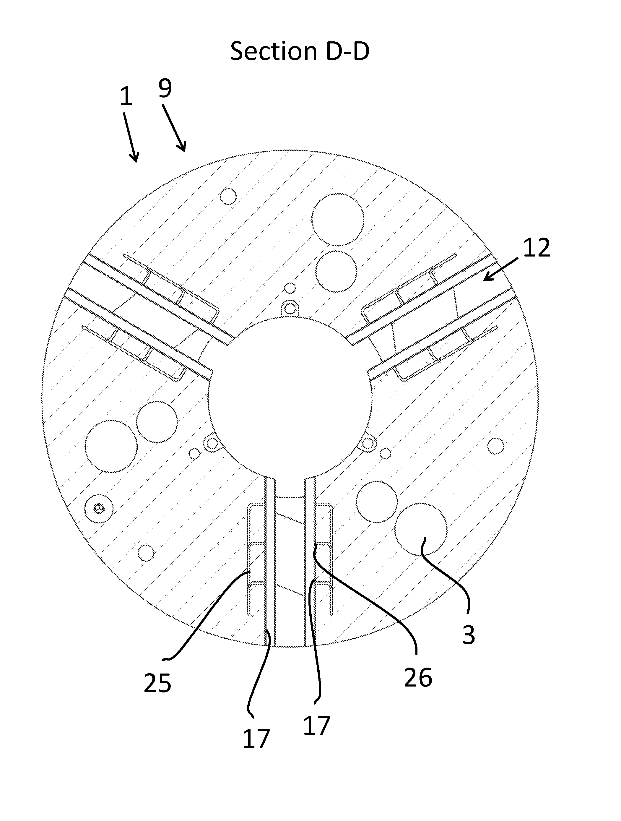
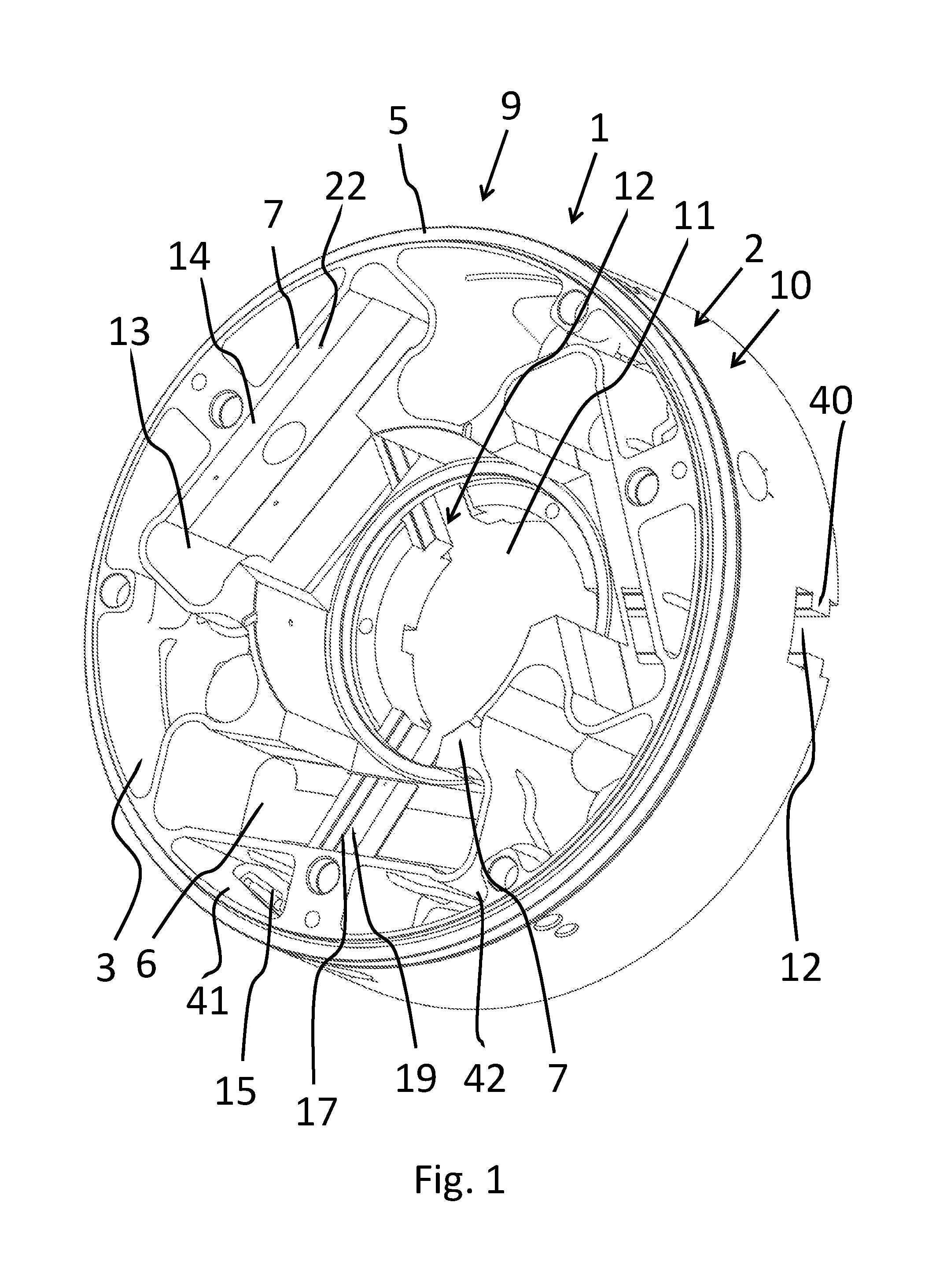
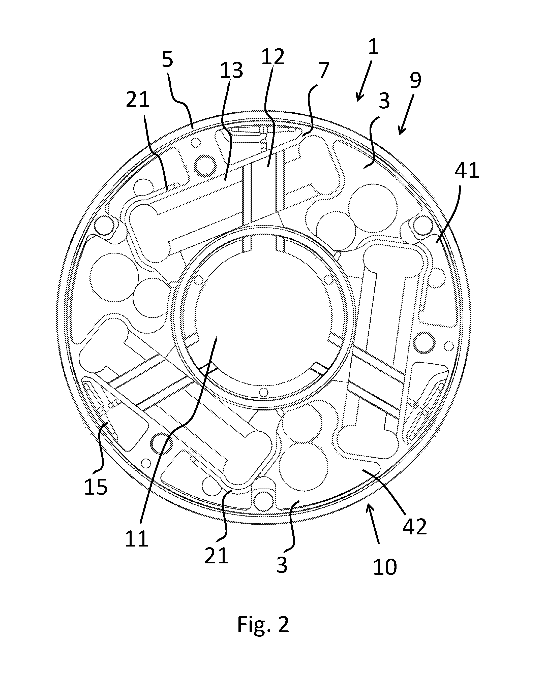
[0052]FIG. 1 shows the perspective view of the first specific embodiment of clamping device 1 according to the invention, which is designed as a chuck 9. Chuck 9 comprises a chuck body 10 as base body 2, which is surrounded by an outer wall 5 and has a passage 11 in the center. Chuck body 10 is furthermore assigned a base plate 6. Three guide receptacles 12 extend from passage 11 to outer wall 5, guide receptacles 12 being disposed distributed at regular intervals around the circumference of passage 11. Guide receptacles 12 each comprise two guide rails 40 and two diametrically opposed guide surfaces 17, along which clamping jaws may be moved. Passage 11 is surrounded by an inner wall 7. In addition, the interior of chuck body 10 is divided into multiple base structures by the formation of an inner wall (cavities 3, wedge bar receptacles 13, guide receptacles 12, passage 11 and line systems 15, 23): wedge bar receptacles 13 are disposed distributed at regular intervals around the ci...


PUM

PropertyMeasurementUnit
temperatureaaaaaaaaaa
circumferenceaaaaaaaaaa
centrifugal forceaaaaaaaaaa

Abstract

A clamping device for clamping a workpiece, having a base body and at least one clamp which is adjustable relative to the base body, at least one cavity is formed in the base body, a reinforcement is formed in the cavity.

Description

[0001]This nonprovisional application claims priority under 35 U.S.C. §119(a) to German Patent Application No. 10 2015 103 122.1, which was filed in Germany on Mar. 4, 2015, and which is herein incorporated by reference.BACKGROUND OF THE INVENTION[0002]1. Field of the Invention[0003]The invention relates to a clamping device for clamping a workpiece, comprising a base body and at least one clamp that is adjustable relative to the base body.[0004]2. Description of the Background Art[0005]Clamping devices of this type are known from practice, these clamping devices being characterized by an extremely massive design to achieve a high load tolerance, i.e. they are associated with a high weight. Due to the massive construction, vibrations are conducted undamped within the base body of the clamping device and are transmitted to the workpiece. This results in a higher wear on the clamping device and can limit the processing or transport of sensitive workpieces.[0006]In chucks, the high wei...

Claims


Application Information

Patent Timeline
Patent Type & Authority Applications(United States)
IPC IPC(8): B23B31/02
CPCB23B31/02B33Y80/00B23B2222/04B23B2222/21B23B2222/98B23B2222/48B22F7/006B23B2222/88B23B2222/44B23B2250/12B23B2231/24B23B2231/32B23B2222/84B25B11/00B23B31/16287B25B1/02B25B1/241B23B31/16B23B31/16045
Inventor SCHWEIGERT, EDUARD
Owner ROHM GMBH
Learn More