
Laminating body

Active Publication Date: 2016-08-25
GIESECKE & DEVRIENT MOBILE SECURITY GMBH
View PDF3 Cites 0 Cited by
  • Summary
  • Abstract
  • Description
  • Claims
  • Application Information

AI Technical Summary

Benefits of technology

The invention is about a laminating body with an imprinted structure that can be applied to a foil during lamination. The structure is raised and hard, and can be easily detached without damage or residue. The process of imprinting the structure is simpler and faster than other methods, and it is resistant to heating. The laminating body can also be printed with the structure outside of production facilities, saving time and costs and ensuring flexibility. A thermally stable lacquer is recommended for printing the structure to ensure its long life when heated during lamination.

Problems solved by technology

This not only causes high costs, but also results in relatively long production times and delivery times, which leads to a lack of flexibility and low reaction times for the laminate product manufacturer, in particular in the case of laminate products to be manufactured urgently.
This method is likewise disadvantageous when only small batches of laminate products are to be manufactured, because this requires a frequent change of the laminating body solely due to changed embossed structures.

Method used


Image

  • Laminating body
  • Laminating body
  • Laminating body

Examples


Embodiment Construction

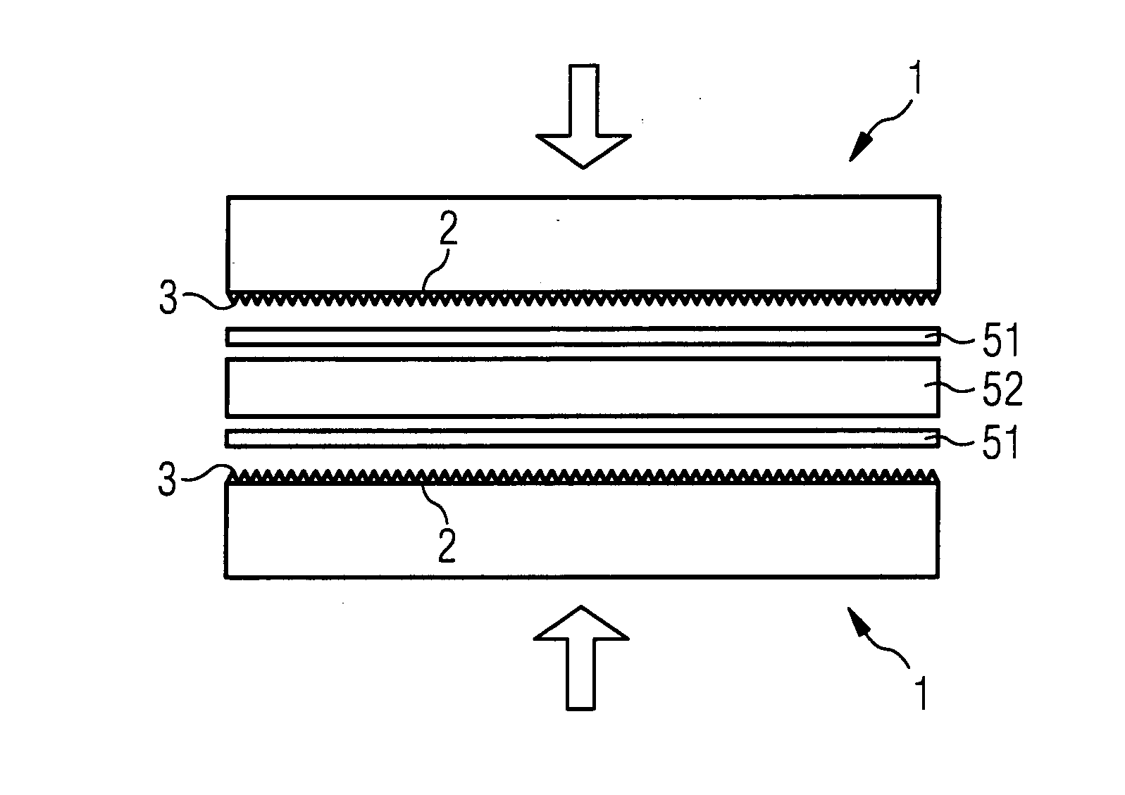
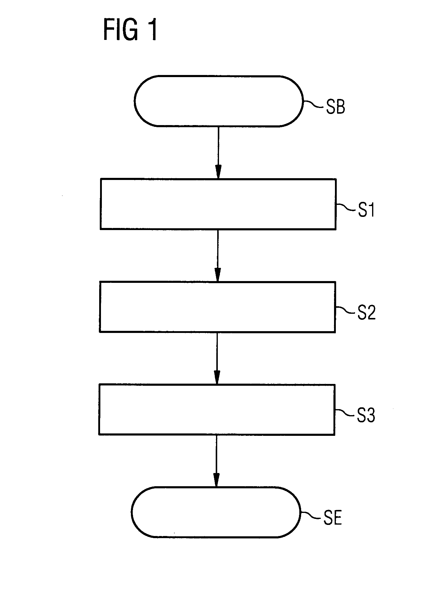
[0032]FIG. 1 shows schematically the steps of a method for imprinting a structure on a laminating body 1 and subsequent employment of the laminating body 1 for lamination.

[0033]After the beginning SB of the method, a laminating body 1 is first made available in step S1 and optionally so prepared that it can subsequently be printed in step S2. The laminating body 1 can consist in principle of any sufficiently heat-resistant and stable material. In the present case there is employed a laminating body 1 of metal, preferably of chromium steel or brass or nickel-plated brass or chromium-plated brass. Particularly preferably, the laminating body of metal is high-gloss on one or both sides.

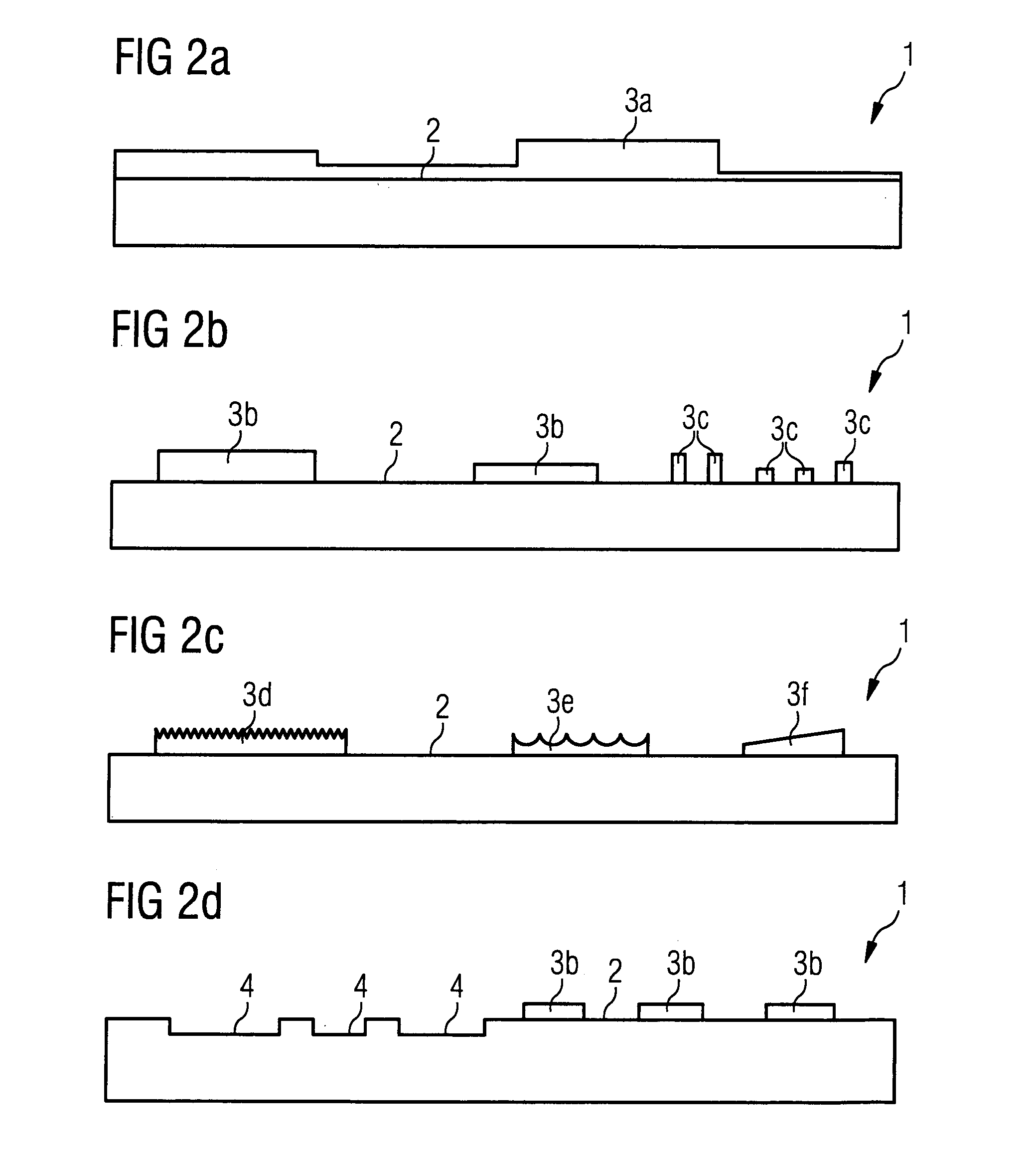
[0034]For preparing the imprinting, the laminating body 1 is optionally cleaned or polished. Also, there can be applied to the pressure area 2 of the laminating body 1 an adhesion promoter or another chemical substance that facilitates or makes possible the printing of the laminating body 1 in step S2. S...


PUM

PropertyMeasurementUnit
Pressureaaaaaaaaaa
Areaaaaaaaaaaa

Abstract

A laminating body for laminating a foil onto a substrate includes a pressure area on which there is imprinted a structure which forms an embossing in the foil upon lamination of the foil onto the substrate.

Description

BACKGROUND OF THE INVENTION[0001]A. Field of the Invention[0002]This invention relates to a laminating body for manufacturing laminate products by laminating a foil onto a substrate, and to a method for manufacturing such a laminating body and a method for manufacturing a laminate product by means of the laminating body.[0003]B. Related Art[0004]Relevant laminate products in the present case are primarily value documents, identity and identification documents, chip cards or other card-shaped data carriers and value carriers or the like. The substrate can consist here of an almost arbitrary suitable material, e.g. of paper, plastic or the like.[0005]It is known to provide a pressure area of laminating bodies employed upon lamination with a structure in the form of depressions by milling, etching or engraving, said structure being embossed into the laminated-on foil upon lamination and being perceptible in the resulting laminate product. Such embossings can serve e.g. as security feat...

Claims


Application Information

Patent Timeline
IPC IPC(8): B32B38/06B32B38/00B32B37/00
CPCB29C33/38B29C33/424B29C59/02B29C59/04B30B3/005Y10T156/1039B32B37/0046B32B38/06B32B38/145B32B2311/00B32B2425/00B30B15/062
Inventor HUBER, PETERMINKS, ANDREASKOHL, KLAUS
Owner GIESECKE & DEVRIENT MOBILE SECURITY GMBH
Learn More