
System and method for distribution and dispensing of beverages

a beverage and system technology, applied in the field of beverage system and method, can solve the problems of high cost of steel containers or kegs, high cost of steel construction, etc., and achieve the effect of cost-effective and secure seal, simple production and simple structur

Active Publication Date: 2017-08-08
PETAINER LIDKOPING AB
View PDF94 Cites 11 Cited by
  • Summary
  • Abstract
  • Description
  • Claims
  • Application Information

AI Technical Summary

Benefits of technology

[0013]The fact that the container is freestanding and disposable as well as formed in a single piece provides a cost-efficient container that can be produced from a preform at the location where the container is later supposed to be filled. After use the empty container can be efficiently discarded without taking up a significant amount of storage space. In one embodiment the container system replaces a conventional keg system for draught beer. Compared to regular steel containers that are utilised for draught beer, the inventive container is more cost-efficient in more than one aspect. First, it is less costly to produce in terms of raw material costs, power consumption and processing steps. Second, since the containers are blow moulded from preforms on demand at the location in which it subsequently will be filled, they do not require nearly as much storage space. Third, in the case of steel containers, there is a need for an organisation handling the returned containers, which obviously increases the costs further. Because of the fact that the container of the inventive system is freestanding and durable, there is no need for the provision of an outer, protecting and / or supporting structure. In use the container is simply placed standing upright without any support, and connected to a standard dispensing system. This is obviously more cost-efficient than known solutions, but it also requires less space than if an additional supporting structure needs to be used.
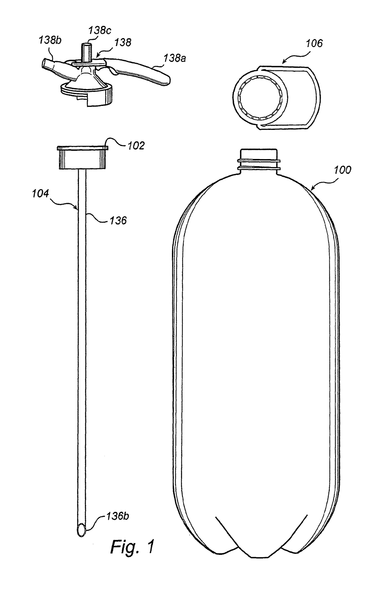
[0032]This inventive method makes it possible for a producer of beverages to have in-house production and filling of containers, just purchasing the preforms and the tube / valve structure from an external supplier. The preforms do not require a massive storage space, and since the containers are blow moulded in the processing step preceding the filling step—after which they are loaded and delivered to a customer—the total storage space needed is substantially reduced as compared to the standard keg system. Further, the producer of beverages can deliver the filled and capped container to customers at a low cost, again compared to the conventional keg system, and a threshold to expand into new markets is significantly reduced due to the reduction of associated costs. The tube / spear structure is generally assembled prior to being attached to the container. Depending on the type of closure element, this can be performed before or after filling of the container, which will be described later on. Hence, the step of filling the container and the step of providing the container with a tube structure can occur in reversed order.

Problems solved by technology

The steel containers or kegs are costly to produce and to keep in stock for a supplier of beverage, and after they have been emptied and prior to their return trip they demand a large storage volume for an end user.
The above publication addresses the mentioned problem associated with steel containers but still only provides a partial solution since the container still is a relatively expensive and elaborate construction.
This known system also requires several accessories which makes it expensive and complicated.
This has an injurious effect on the hygiene in the container and the quality of the water can consequently not be vouched for.
Thick-walled containers result in increased production and transportation costs, relative to thin-walled containers.
Further, the thick-walled containers demand larger resources in terms of disposal systems.
This is especially a problem in developing countries where drinking water often needs to be transported in various kinds of containers to areas that do not have access to safe running water.

Method used


Image

  • System and method for distribution and dispensing of beverages
  • System and method for distribution and dispensing of beverages
  • System and method for distribution and dispensing of beverages

Examples


second embodiment

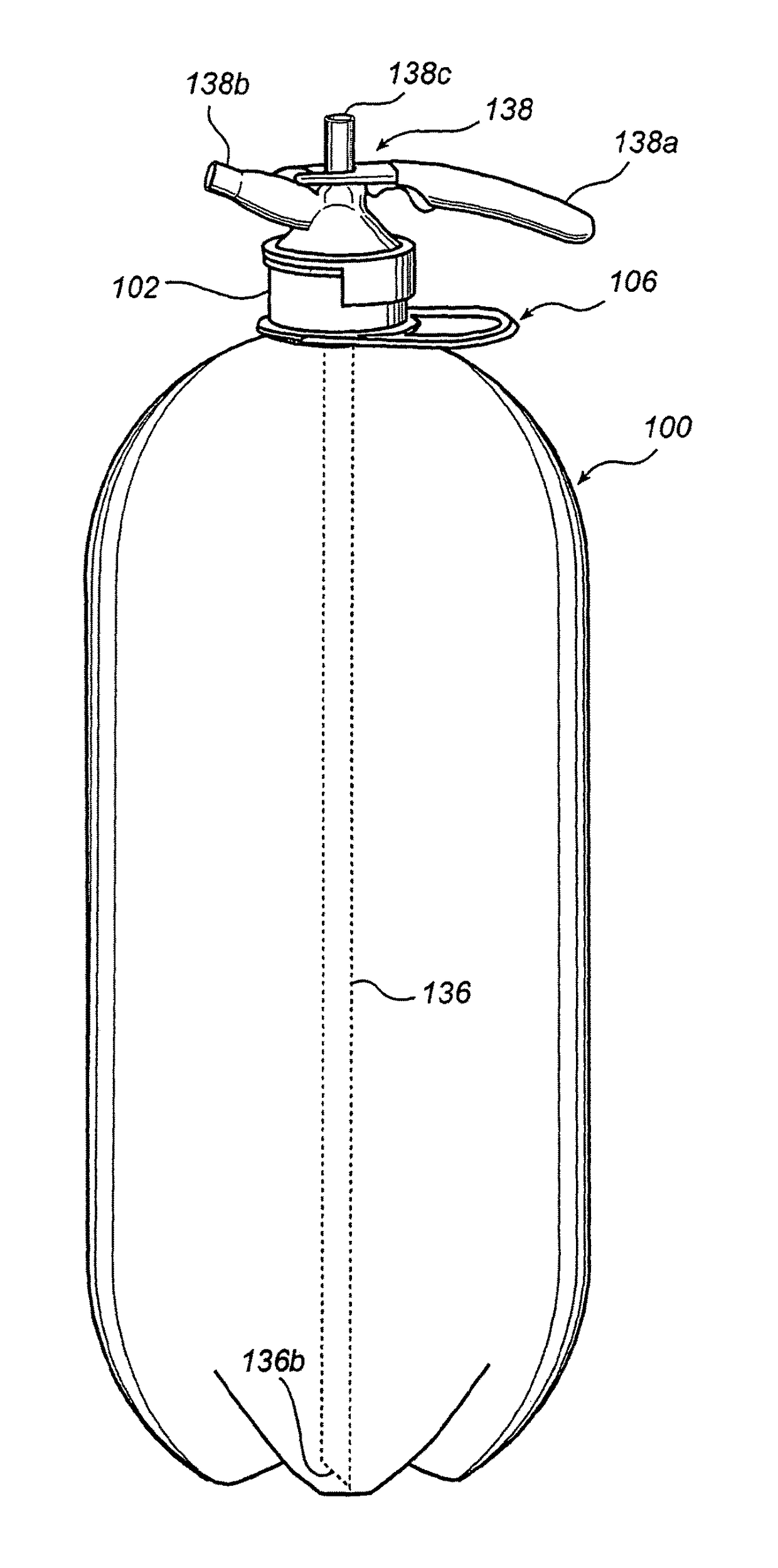
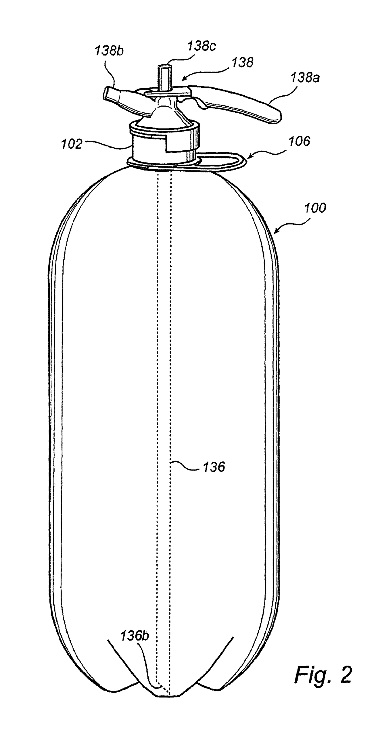
[0055]Filling of the disposable container 100 with a carbonated beverage (such as beer) is generally conducted in the following manner. Once the spear structure 104 is assembled as a unit 102, 136 it is attached to the container 100 with the tube 136 inserted into the container 100. Then the container 100 is placed upside down in a filling station (not shown). Air inside the container 100 is flushed out by carbon dioxide, and an overpressure (a filling pressure) is established. These measures are taken in order to minimise the risk of foam being produced during filling, which would slow down the filling procedure. If the risk of foam production is low, said measures can obviously be cancelled. During filling the annular valve member 128 is depressed so that beverage can be injected into the container 100. Gas contained in the container 100 is forced out upwards through the elongate tube 136. The container 100 could also be filled prior to the arrangement of the spear structure 104, ...

first embodiment

[0060]FIG. 7 shows an alternative and less complex closure element in the form of a pierceable plastic cap 140. Before being attached to the mouth portion 108 of the container 100 the cap 140 is provided with an elongate tube 136′ similar to the elongate tube 136 of the The tube is indicated by phantom lines extending from the cap 140. Prior to being provided with the pierceable cap 140 and the tube 136′, the container 100 is filled in the following manner: Air is first flushed from the container 100 which stands upright, by use of carbon dioxide or nitrogen in order to make the filling procedure more efficient. A filling pressure is optionally provided. An elongate filling nozzle (not shown) is inserted into the container 100 which is kept upright, and the beverage is filled into the container 100. The filling rate is slower at the beginning until approximately a decimeter of beverage is filled into the container 100, and the nozzle orifice is submerged. Then, the filling rate inc...


PUM

PropertyMeasurementUnit
volume capacityaaaaaaaaaa

Abstract

A method for the distribution and dispensing of beverages utilizes a one-way system including a disposable and freestanding container. The container is blow-molded in one piece from a preform of plastics. The system also includes a tube to be inserted in the container and a closure cap. The container can be filled, distributed to an end user and connected to standard beverage dispensing structure. After use, the empty container is collapsed and discarded.

Description

[0001]This application is the U.S. national phase of International Application No. PCT / SE2006 / 001355, filed 29 Nov. 2006, which designated the U.S. and claims priority to Sweden Application No. 0502604-2, filed 29 Nov. 2005, and claims the benefit of U.S. Provisional Application No. 60 / 740,282, filed 29 Nov. 2005, the entire contents of each of which are hereby incorporated by reference.TECHNICAL FIELD[0002]The present inventive concept concerns a system and a method for distribution and dispensing of beverages.BACKGROUND ART[0003]When supplying relatively large amounts of beverage, in the order of tens of liters, to an establishment it is known to use refillable steel containers, in the case of beer and such, or heavy duty refillable or recyclable plastic containers, in the case of water for water dispensers. The steel containers or kegs are costly to produce and to keep in stock for a supplier of beverage, and after they have been emptied and prior to their return trip they demand...

Claims


Application Information

Patent Timeline
Patent Type & Authority Patents(United States)
IPC IPC(8): B67D1/04B67D1/08B65D1/02B65D47/24B67C3/30B29C49/06B65D81/26B67C3/22B29K67/00B29K77/00B29L31/00B67D7/78B67D99/00
CPCB67D1/0832B65D1/0276B65D1/0284B65D47/247B67C3/30B29C49/06B29K2023/06B29K2067/00B29K2067/046B29K2077/00B29K2623/06B29L2031/7158B65D81/266B67C2003/227B67D2001/0812B67D2001/0824B29C2949/0715B67D1/08B29C49/22B29C49/4273B29K2105/258B65D1/0246B65D23/02B65D23/0828B65D81/24B67C7/00B67D1/0801
Inventor QUASTERS, MIKAEL
Owner PETAINER LIDKOPING AB
Learn More