
Method and apparatus for directly digitizing microwave signals

a microwave signal and microwave technology, applied in the field of direct digitization of microwave signals, can solve the problems of reducing the reproducibility and accuracy of output signals, affecting the reproducibility of output signals, and requiring a lot of test effort, so as to reduce the number of analog circuit components in the device of the mentioned kind

Inactive Publication Date: 2005-06-28
VEGA GRIESHABER GMBH & CO
View PDF20 Cites 8 Cited by
  • Summary
  • Abstract
  • Description
  • Claims
  • Application Information

AI Technical Summary

Benefits of technology

[0007]An object of the present invention consists in providing an apparatus, by means of which the number of analog circuit components in devices of the mentioned kind may be reduced, and the aforementioned disadvantages thus are at least reduced.
[0018]In that several A / D converters are provided, an A / D converter may work alternatingly for each pulse, and the corresponding value may be stored in the terminal memory unit, so that the sampling rate of the individual A / D converter may be reduced.
[0019]Thus, it may be possible according to an exemplary embodiment of the present invention to perform digitizing with usual components in spite of the immensely high frequencies, a fact which eliminates the disadvantages of analog components and in particular the disadvantages of the previous mixer.
[0021]In that several intermediate memories connected in series are provided, it is possible to use slower-working memory chips, which hence are more cost-efficient.
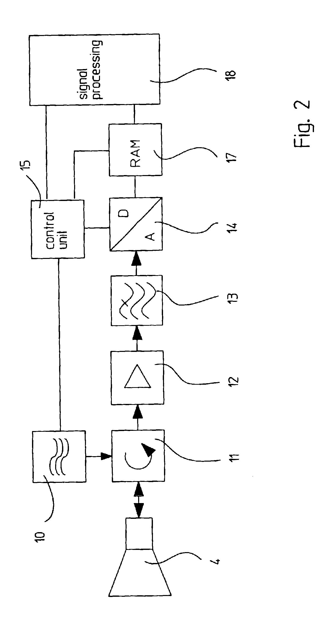
[0026]As already mentioned above, according to a forth aspect of the invention, an analog memory unit is connected between a reception circuit and an A / D converter. In this case the design is based on the principle of FISO (Fast In Slow Out). The analog memory unit may be designed as, for example, shown in DE 30 13 256 A1, U.S. Pat. No. 5,200,981, or U.S. Pat. No. 5,144,525. The analog memory unit may alternatively be designed basically like a circuit sold under the name “CompuScope 85G” of the company Tectronix. The analog memory unit makes it possible to store the received microwave signal (analog signal) without modifying its frequency. Furthermore, an A / D converter can be used which samples the read out analog values with a rate less than the rate with which the analog values are stored in the analog memory unit. By means of such an design, it is possible to use an A / D converter less fast than an A / D converter used in the other exemplary embodiments of the invention.

Problems solved by technology

The use of analog components or analog circuit technology, however, can be subject to disadvantages.
Analog components moreover exhibit temperature dependencies, which have to be considered and cause a rather significant test effort.
Temperature dependencies and component tolerances, in addition, can result in a decrease of the reproducibility and accuracy of the output signals, and have to be minimized or compensated by an additional effort.
An disadvantage may also to be seen in that modifications in the functional mode of such analog circuits can only be performed at an important effort.

Method used


Image

  • Method and apparatus for directly digitizing microwave signals
  • Method and apparatus for directly digitizing microwave signals
  • Method and apparatus for directly digitizing microwave signals

Examples


Embodiment Construction

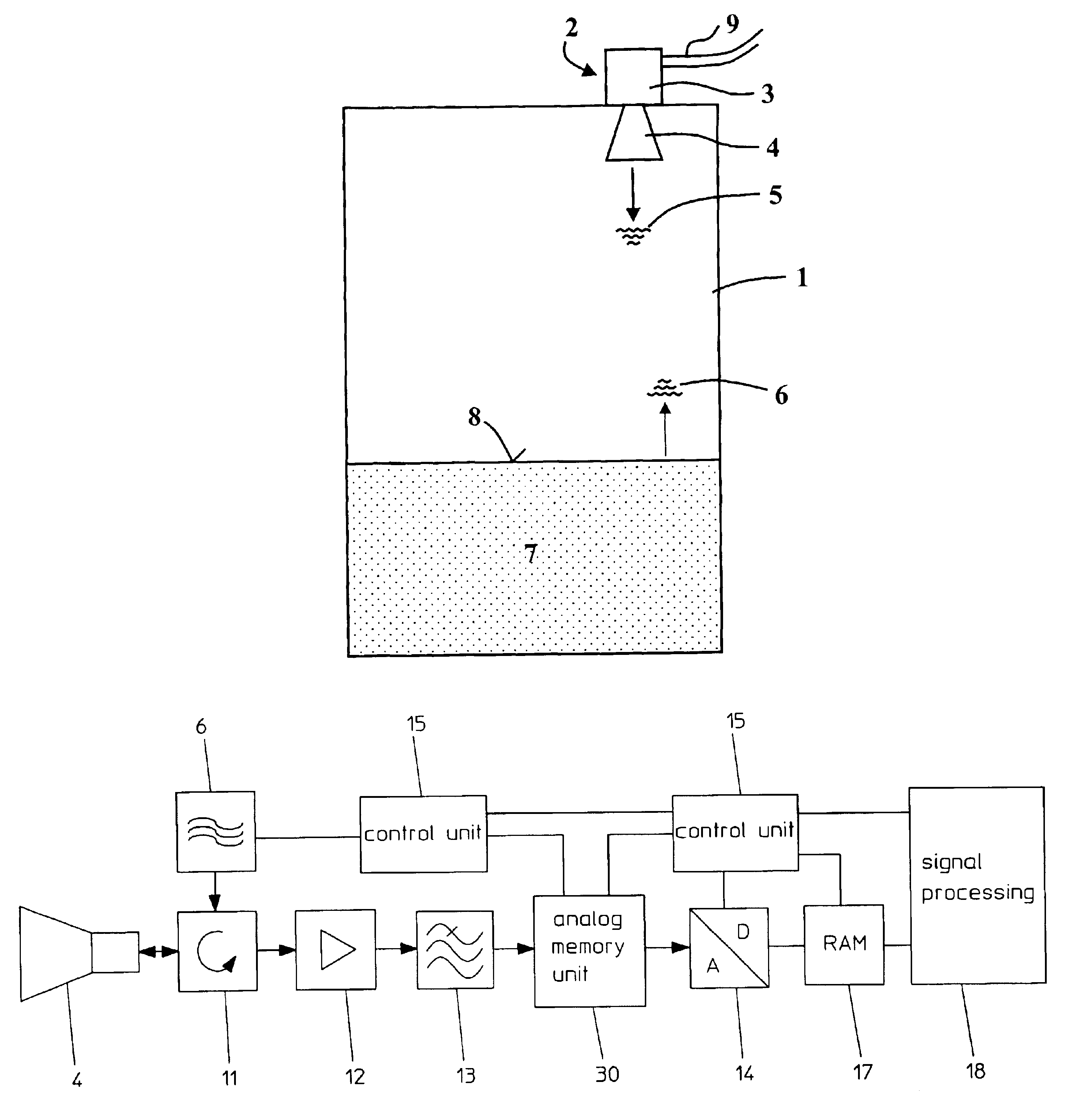
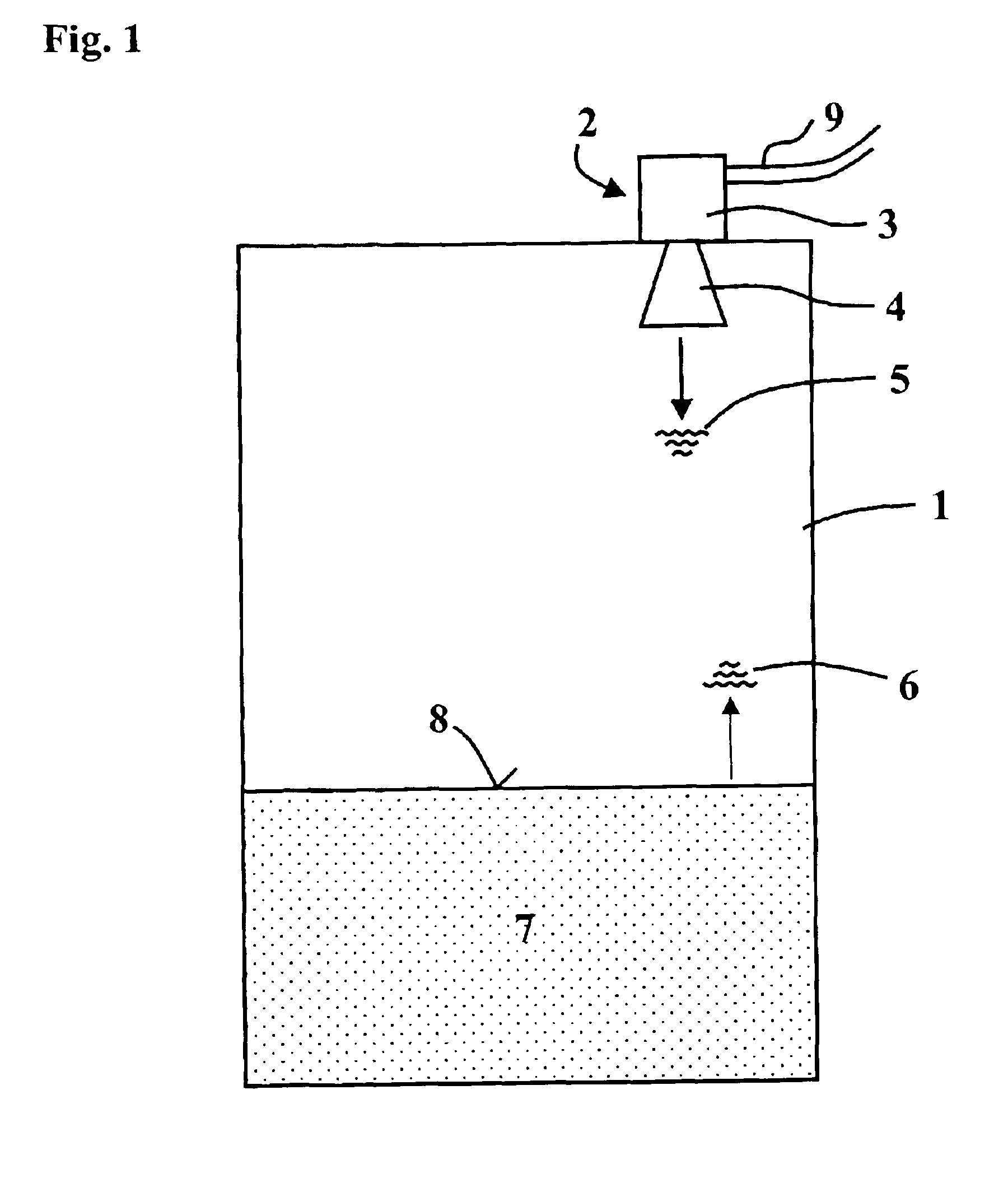
[0040]With reference to FIG. 1 and FIGS. 6-9, the principle working method and the principle structure of a filling level measurement device will initially be explained. As can be seen from FIG. 1, in the cover zone of a receptacle 1, a filling level measurement device 2 is mounted, that is composed of an electronic unit 3 and a horn antenna 4. The filling level measurement device 2 is connected with a remote control panel or such like via a two-wire loop 9. Via said two-wire loop 9, which is in particular configured as a 4-20 mA two-wire loop, ensues the communication, as well as the energy supply of the filling level measurement device 2. In the electronic unit 3, microwave pulses are generated and radiated via the horn antenna 4 in the direction of the bulk product 7 present in the receptacle 1. The microwave pulses 5 are reflected at the bulk product surface 8, and are again received by the horn antenna 4 as an echo signal 6.

[0041]The generation of microwave pulses 5 or pulse pa...


PUM


Abstract

Described is a method and an apparatus of directly digitizing microwave signals reflected at a filling product surface of a filling product present in a receptacle, in which method the microwave signals reflected at the filling product surface are sampled unmodified in their frequency, and the therefrom resulting analog values are converted into digital values, with successive digital values being stored in various intermediate memories, and the intermediately stored digital values are read out from the intermediate memories and are stored in a terminal memory unit, to which accesses an evaluation arrangement which determines the filling level height.

Description

PRIORITY CLAIM[0001]This application claims the benefit of U.S. Provisional Patent Application Ser. No. 60 / 315,272 filed on Aug. 28, 2001 and German Patent Application Serial No. 101 40 821.8 filed on Aug. 20, 2001 which are expressly incorporated herein, in their entirety, by reference.TECHNICAL FIELD[0002]The present invention relates to a method and an apparatus for directly digitizing microwave signals reflected from a filling product surface of a filling product present in a receptacle, as well as to a filling level measuring device working on the transit time principle and emitting microwave signals. Furthermore, the present invention relates to a filling level measurement device working on the transit time principle and emitting microwave signals.[0003]Reduced to the core features and hence expressed in a simplified manner, microwave signals are generated (on a pulse basis or continuously) by a transmitting means in a filling level measuring device of the mentioned kind, and ...

Claims


Application Information

Patent Timeline
IPC IPC(8): G01F23/284G01S13/00G01S13/10G01S7/32G01S7/285G01S7/292G01S13/88
CPCG01F23/284G01S7/292G01S13/103G01S7/32G01S13/88
Inventor LAUN, ROBERT
Owner VEGA GRIESHABER GMBH & CO
Learn More