Nail Clipper

a nail clipper and clipper technology, applied in the field of nail clippers, can solve the problems of finger discomfort, user inconvenience or discomfort, and burden on the user to securely hold the nail clipper,

Active Publication Date: 2016-08-18
YUN WOO SUNG
View PDF10 Cites 1 Cited by
  • Summary
  • Abstract
  • Description
  • Claims
  • Application Information

AI Technical Summary

Benefits of technology

[0009]The thumb ring member further comprises a connection plate member of a predetermined width and length, said connection plate member formed unitarily with the first and second ring members into one piece, and thereby connecting and bridging between a lower portion of the first and second ring members, the connection plate member having a planar upper surface and including a bore formed vertically through the connection plate member, and a fastener coupled to the bore of the connection plate member and allowing the thumb ring member to freely rotate relative to the lever member.

Problems solved by technology

As the metallic tip portions of the plate members are often slippery, and it is burdensome and uncomfortable for the user to securely hold the nail clipper at the narrow and slippery tip portions thereof.
However, since this nail clipper allows only one finger (e.g., the index finger) to the bottom ring member, it is not ideal and causes inconvenience or discomfort to the user.
This is at least because the pressure that is put solely on one finger (e.g., index finger) can cause discomfort on the finger.
Thus, this nail clipper can produce excessive pressure onto the respective contacting fingers (i.e., the thumb and the index finger) that are respectively inserted to the two ring members for operation.
In addition, as two fingers (i.e., the thumb and the index finger) of the user's hand are required to be inserted to the two rings 24 and 38, the gripping posture for grasping the nail clipper is limited by this restriction, and thus, this causes inconvenience to the user.

Method used


Image

  • Nail Clipper
  • Nail Clipper
  • Nail Clipper

Examples


Embodiment Construction

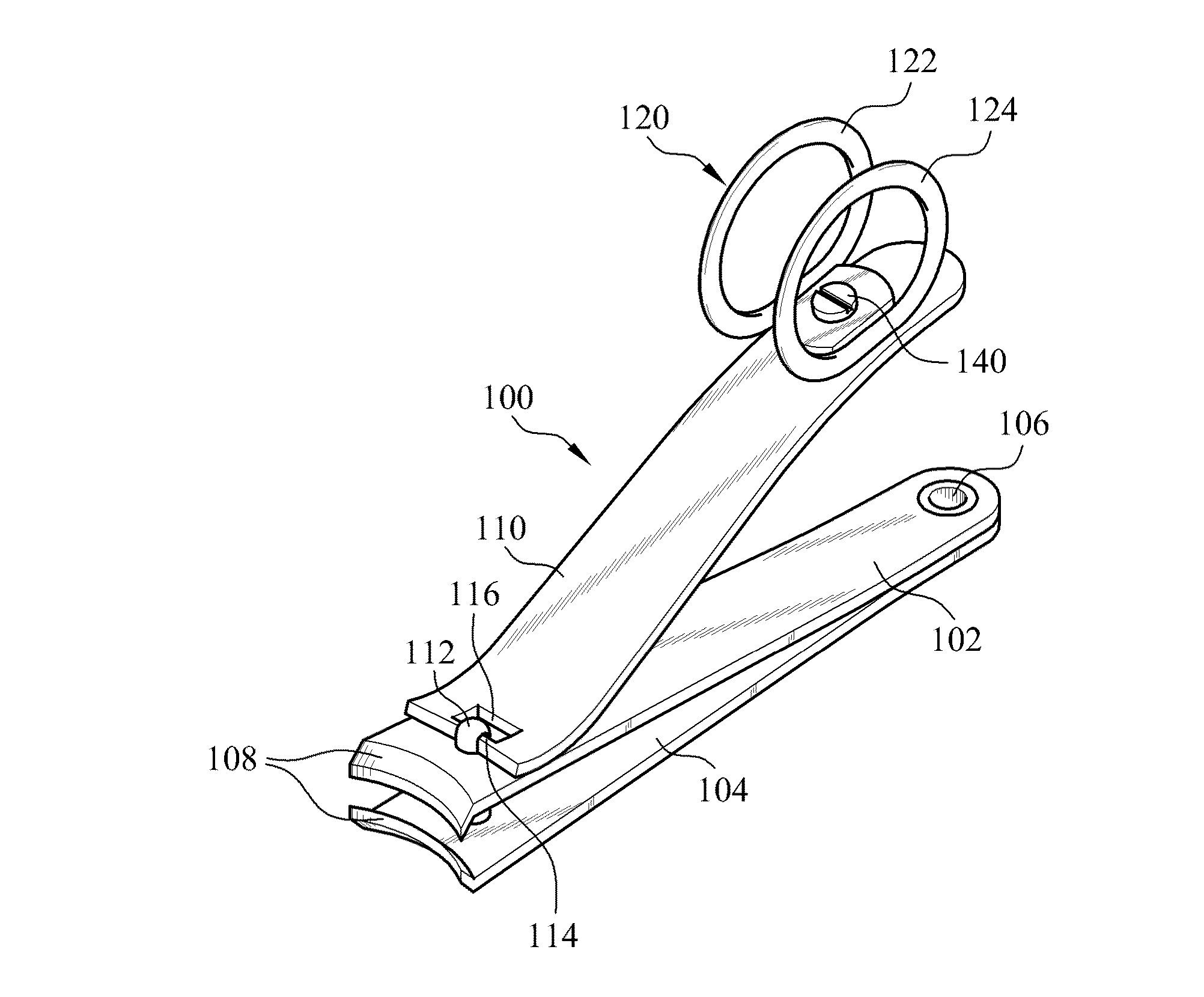
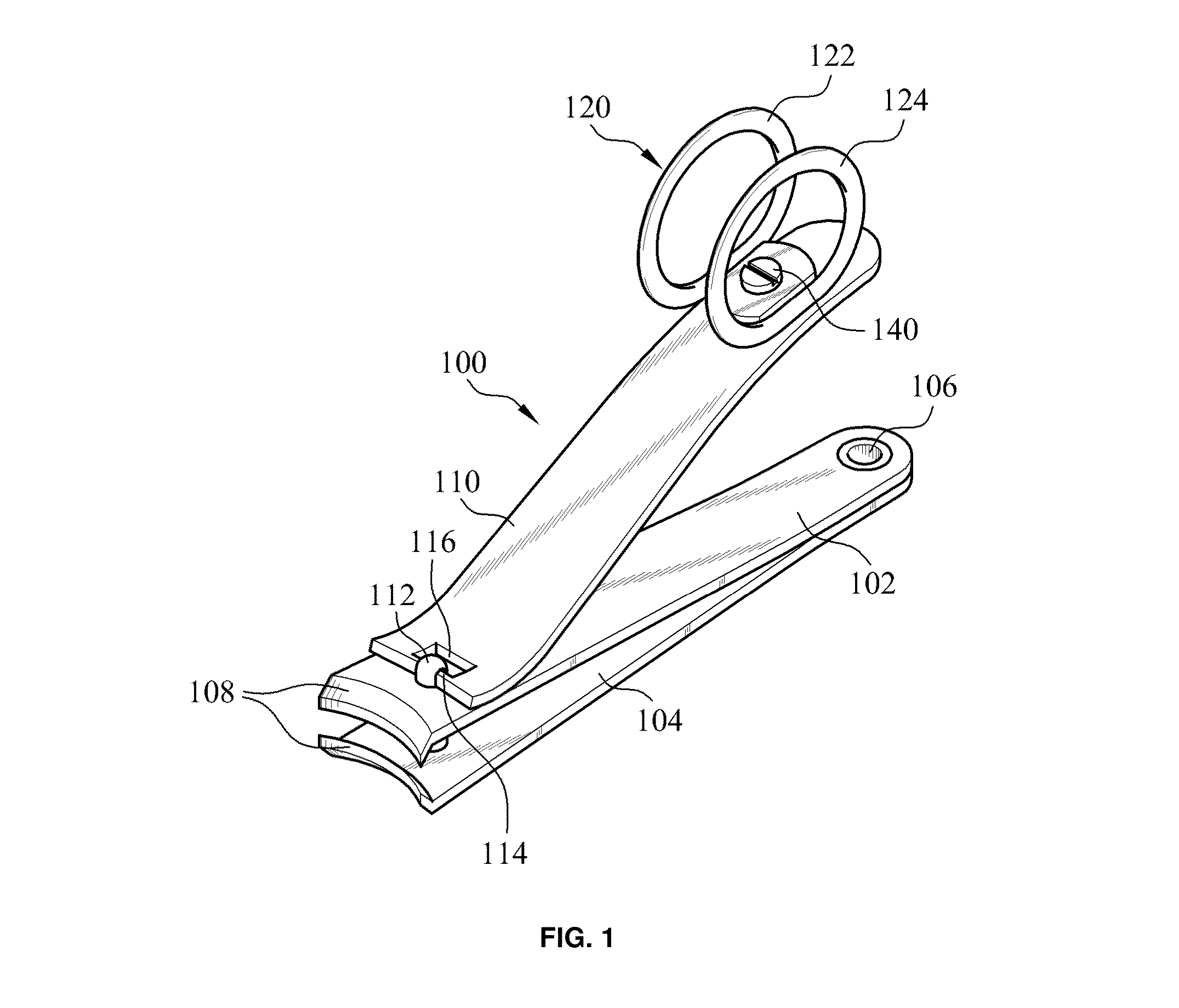
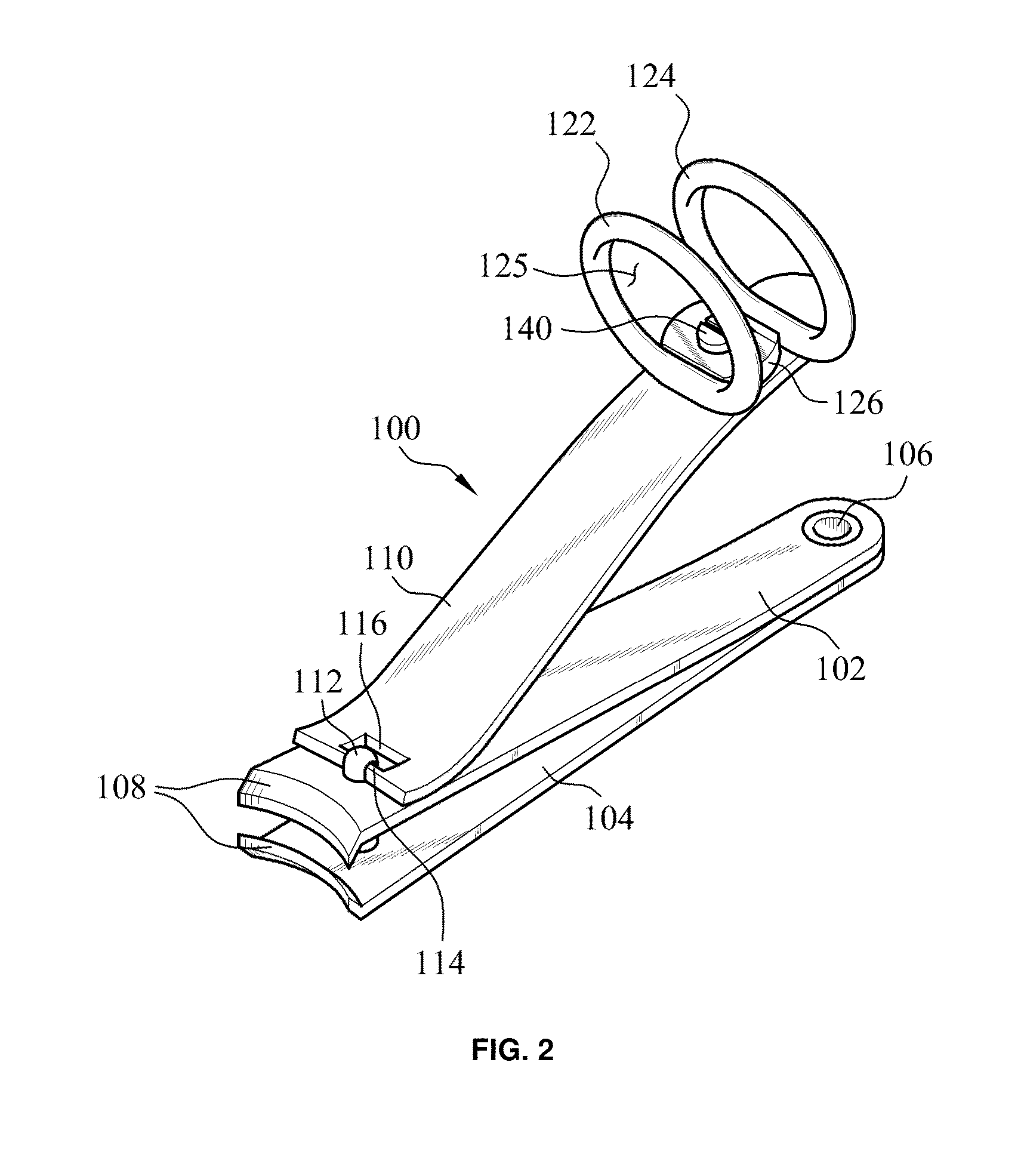
[0023]Referring to the drawings, the nail clippers of the present invention are described herein in detail in association with exemplary or currently preferred embodiments thereof. However, the following descriptions of such embodiments are intended primarily for illustrating the principles and exemplary constructions of the nail clippers of the present invention, and the present invention is not specifically limited to these exemplary embodiments. Thus, one skilled in the art can appreciate or recognize that various modifications and substitutions can be made thereto without departing from the spirit and scope of the present invention. Throughout the disclosure, the same or similar elements and portions thereof are referred and described with the same reference characters for the simplicity and illustrative purposes.

[0024]With reference to FIGS. 1 and 2, the nail clipper according to one preferred embodiment of the present invention is described herein below. As depicted in the dra...


PUM


Abstract

A nail clipper includes a clipper body with a pair of jaws, a lever configured to move the jaws to cut nail, a thumb ring member rotatably mounted to the lever, the thumb ring member having first and second ring members, each defining an inner opening through which a thumb of the user can be introduced. The nail clipper further includes a connection plate member which is formed unitarily with the first and second ring members into one piece and connecting between the lower portions of the first and second ring members, wherein the connection plate member has a planar upper surface and includes a bore formed vertically there-through, and a fastener is coupled to the bore of the connection plate member and allows the thumb ring member to freely rotate relative to the lever.

Description

REFERENCE TO RELATED APPLICATIONS[0001]This application claims the priority benefit of U.S. Provisional Patent Application No. 62 / 116,153 filed on Feb. 13, 2015, the entire contents of which are incorporated herein by reference.FIELD OF THE INVENTION[0002]The present invention relates to a nail clipper having a ring member (in particular, a thumb ring) mounted to a lever member of the nail clipper, in which the ring member is configured to allow a user to insert its thumb thereto, and thus, facilitating easy and firm holding of the clipper with the thumb and other fingers of the user.BACKGROUND OF THE INVENTION[0003]Nail clippers typically include first and second plate members that are joined together at one end, and having a pair of jaw portions at the opposite end thereof, and an operating lever coupled to the plate members for moving the jaws from an open position to a nail cutting position. The first and second plate members of such conventional nail clippers are made of polish...

Claims


Application Information

Patent Timeline
Patent Type & Authority Applications(United States)
IPC IPC(8): A45D29/02
CPCA45D29/02
Inventor YUN, WOO SUNG
Owner YUN WOO SUNG
Why Eureka
Try Eureka