
Roller covered with covering comprising woven fabric, and apparatus employing same

Active Publication Date: 2016-08-11
SANWA TECHNO
View PDF3 Cites 8 Cited by
  • Summary
  • Abstract
  • Description
  • Claims
  • Application Information

AI Technical Summary

Benefits of technology

The present invention provides a solution for the problems with conventional rollers used in various apparatuses. The rollers have issues with fraying of yarn, dislocation from the rotating support member, and high costs. The invention provides a roller with woven fabric that prevents fraying and dislocation, while also being cost-effective. The woven fabric can include elastic fiber or materials that have low coefficient of friction, making it more resource-conserving and energy-efficient. The invention also allows for easy replacement of the covering without replacing the rotating support member. The roller can be used in various apparatuses and can contribute to conservation of resources, energy, recycling, and low cost.

Problems solved by technology

Where such a roller conveys a conveyed object in the form of sheet-like paper, film, fabric, or the like, paper dust, dust, fibrous waste, and the like will adhere to the surface of the roller, causing degradation of conveyance characteristics.
However, with conventional coverings, where the covering is constituted from a fibrous or filamentous substance, rubbing contact with the conveyed object and compression under load has caused occurrence of fraying due to breakage of filaments, and as this fraying has progressed it has caused occurrence of problems affecting conveyance characteristics and other such functions.
However, where coatings are employed, sliding contact causes the coating layer to wear, as a result of which there is the problem that life is shortened.
To increase life, it therefore becomes necessary to increase the thickness of the coating layer, as a result of which there is the problem that manufacturing cost is increased.
Where tubing comprising such materials is employed there will be the problem of achieving adhesion to the core.
Where such resin-type heat-shrink tubing is employed, circumstances related to tubing manufacturing method ordinarily cause the surface to be slippery and to have poor gripping characteristics.
They are therefore not suited for applications where conveyed objects are conveyed under low load.
However, with rollers employing such resin tubing, because circumstances related to manufacture of the tubing cause the inner and outer surfaces to be slippery, while they are appropriate as rollers where smooth surfaces are required, occurrence of slipping and the like can result in feed nonuniformities in applications where conveying occurs with nips at low loads.
Moreover, where scratches or the like appear on the tubing, contaminant adheres to such scratches, as a result of which defects are produced on the conveyed object.
Coverings for rollers requiring recesses and projections at the surface thereof do not lend themselves to manufacturing methods.
Furthermore, where tubing comprising woven fabric and / or knit fabric is employed, heat-shrink material is employed at the yarn and heat-shrinking is carried out to achieve intimate contact, but there is the problem that there is fraying of yarn at the end faces, as a result of which there is the issue that processing must be carried out at the end faces, meaning that processing at the end faces is required.
Moreover, conventional woven fabric coverings are constituted from a single weave pattern, and so such coverings cannot accommodate diverse rollers.
Next, with rollers used for ventilation, for cooling, or for suction, because holes are ordinarily formed on the surface of the roller, there is the problem that processing costs for carrying this out are high.
However, where a covering comprising ordinary woven fabric covers and engages with a cylindrical body, with conventional mesh-like woven fabric having air permeability, as this is nothing more than the intersections of warp yarn and weft yarn, there is a tendency for occurrence of fraying due to breakage of yarn and of runs in the material as a result thereof and there is moreover a need to carry out prevention of fraying at the open ends of the cylindrical covering.
Thus, with suction rollers, problems include damage to the surface of the sheet, positional dislocation during travel due to conveyance, offset defects, and so forth, as a result of which fabrication of micropores, damage to the roller surface, burrs, and so forth are problems.
These have also therefore been a factor in increasing cost as attempts have been made to improve the foregoing.
Moreover, with conventional ordinary rubber rollers which are rollers employed for conveyance or feeding of paper and the like, rubber rollers made up of rubber layer(s) at the surface thereof have such problems as the fact that gripping characteristics with respect to paper deteriorate due to contamination at the surface as a result of paper dust or the like and wear of the surface, and the fact that there will be misfeeds and so forth in accompaniment to this deterioration in gripping fabrication.
Moreover, because the surface is solid, there has been the problem that it has been impossible to avoid contamination of the rubber surface, some apparatuses even being provided with a member which carries out cleaning of the roller surface.
What is more, due to the fact that in the conventional art there is no technology that has been established which can accommodate the low-variety / small-lot-size style of production that has come to be seen in recent years, each time that a roller is to be fabricated it has been necessary to first develop a suitable manufacturing method.

Method used


Image

  • Roller covered with covering comprising woven fabric, and apparatus employing same
  • Roller covered with covering comprising woven fabric, and apparatus employing same
  • Roller covered with covering comprising woven fabric, and apparatus employing same

Examples


working examples

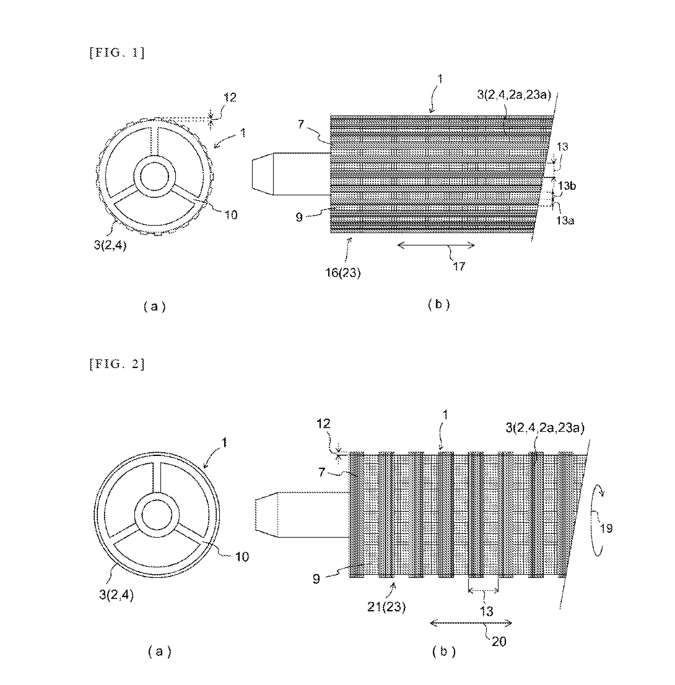
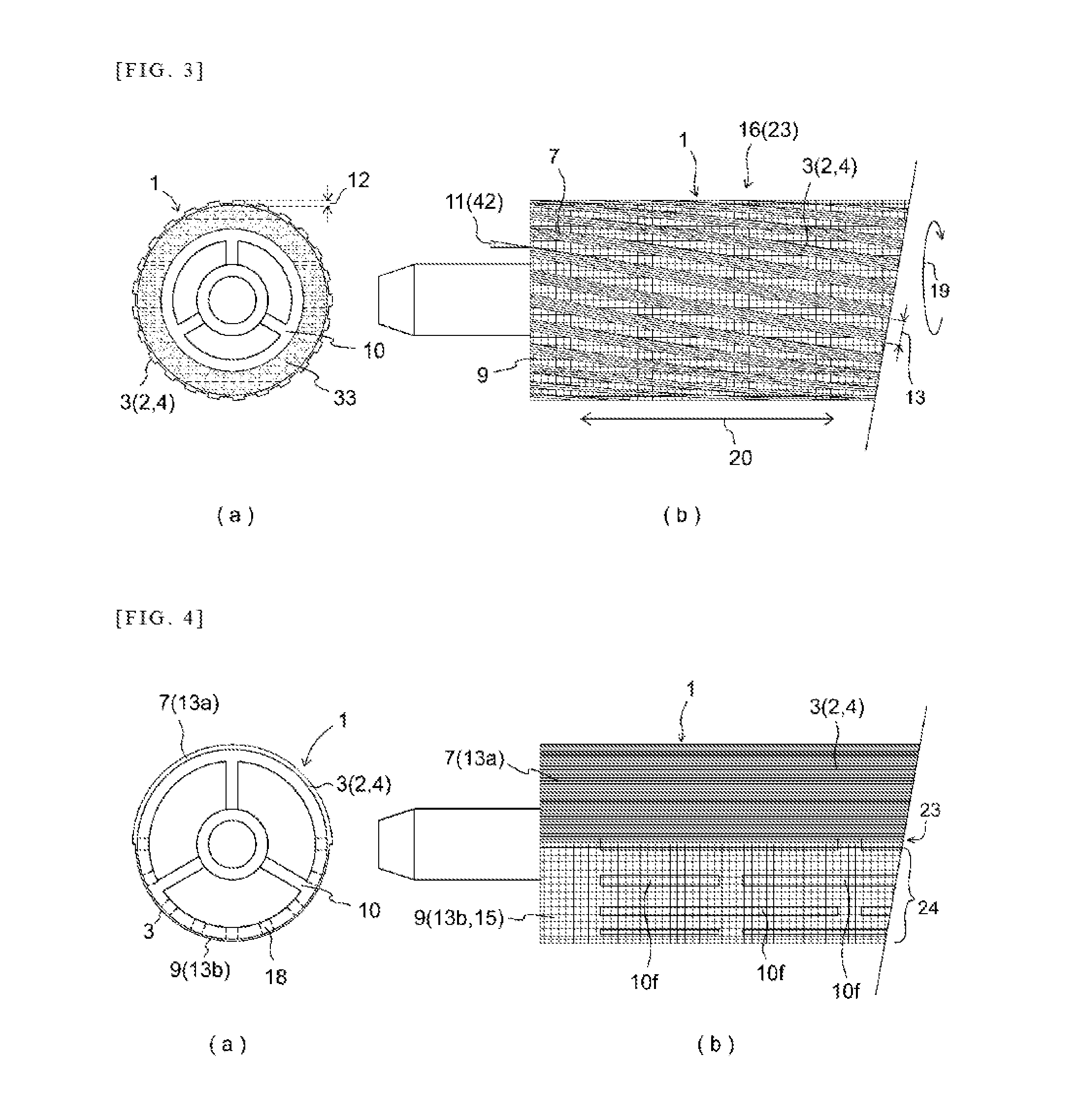
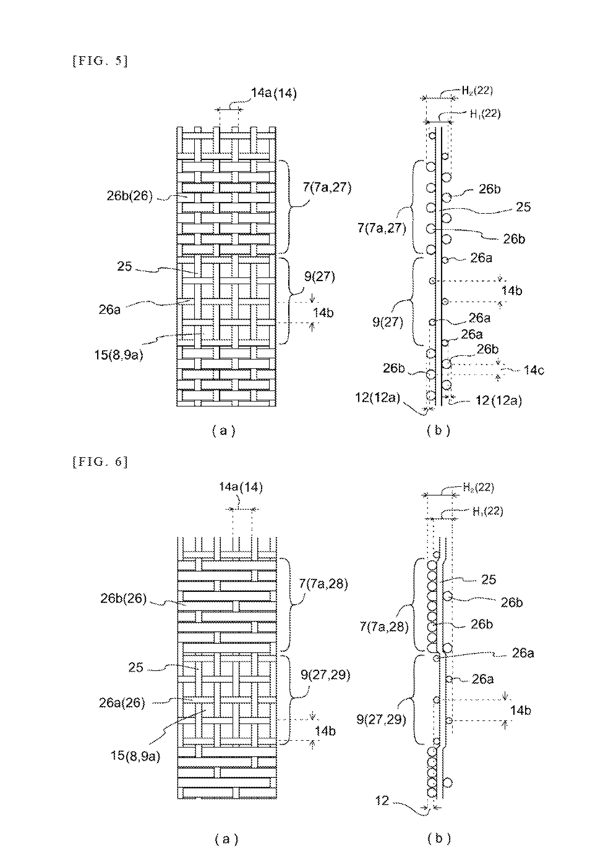
[0113]TABLE 1 shows working examples of woven fabric 2 constituting covering 3 at rotating support member 10. Indicated at Working Example 1 and Working Example 2 in TABLE 1 are coverings 3 in which steps 12 are formed by portions made in satin weave 28 and portions made in plain weave 27 constituting combination of weave patterns and diameters of yarns 5 at weave patterns making up sheet-like non-gap-forming portions 7 and gap-forming portions 9. As indicated at Working Example 1 and Working Example 2, it was possible to adjust air permeability attributable to gap-forming portion 9 depending on whether monofilament 31 was used at small-diameter warp yarn 26a or soft-twist multifilament 30 was used at small-diameter warp yarn 26a. Furthermore, even where weft yarn 25 and large-diameter warp yarn 26b at non-gap-forming portion 7 and gap-forming portion 9 were the same, flattening of yarn made it possible to form steps 12 that were larger when soft-twist multifilament yarn 30 was used...


PUM

PropertyMeasurementUnit
Thicknessaaaaaaaaaa
Adhesion strengthaaaaaaaaaa
Permeabilityaaaaaaaaaa

Abstract

A roller which has woven fabric at a surface thereof and which is employed in an apparatus permitting achievement of conservation of resources, conservation of energy. Roller 1 provided with covering 3 includes woven fabric at its surface is idler means or drive means for conveying, supply, of an object, means for air cooling or drying a moving object, rotating means making use of suction of an object, or is for cleaning a contact surface to which roller 1 is opposed, and has at the surface woven fabric 2 with variation or combination of weave pattern(s). The woven fabric 2 includes weaving in a linear pattern of bands or different patterns. It also has open holes including lattice-like gaps 8 or a rectangular pattern 6 for control of air permeability formed from weft yarn 25 and warp yarn 26.

Description

TECHNICAL FIELD[0001]The present invention relates to a roller for moving or conveying sheet-shaped paper, cloth, film, or the like, and to an apparatus employing such a roller; and in particular, in the context of a roller that sucks dust or the like while rotating or to an apparatus employing such a roller, relates to a roller for which friction at a surface thereof is required or a roller for which suction or cooling and possession of air permeability are required, as well as to an apparatus employing such a roller; for example, a roller employed in any of various types of printing apparatus, coating apparatus, calendaring apparatus, slitter apparatus, laminating apparatus, textile processing apparatus, packaging apparatus, automatic cash dispenser, or other such conveyor apparatus or the like comprising a belt conveyor or roller conveyor as well as to an apparatus employing such a roller.BACKGROUND ART[0002]Conventionally, rollers covered with resin tubes or fiber-like substance...

Claims


Application Information

Patent Timeline
IPC IPC(8): B65H27/00B65H5/22
CPCB41F21/00B65H5/06F16C13/00B65H27/00B65H2401/115B65H5/226B65H2404/1112B65H2404/117B65H2404/18B65H2801/12B65H2401/141G03G15/00G03G15/206G03G2215/00683B65H3/10B65H2401/14B65H2401/11B08B1/32
Inventor SHOJI, SUSUMUFUKUI, KAZURO
Owner SANWA TECHNO
Learn More