Receiving apparatus and receiving method

a technology of receiving apparatus and receiving method, which is applied in the field of receiving apparatus, can solve the problems of reducing reception sensitivity and increasing the amount of noise which passes through the lpf, and achieve the effects of reducing noise components, high reception sensitivity, and demodulating user data

Inactive Publication Date: 2016-08-04
LAPIS SEMICON CO LTD
View PDF3 Cites 1 Cited by
  • Summary
  • Abstract
  • Description
  • Claims
  • Application Information

AI Technical Summary

Benefits of technology

[0020]In the present invention, the LPF eliminates the noise components from the frequency converted signal obtained by performing a frequency conversion on received signal which is the result of receiving wireless transmission wave. The passband width of the LPF is set at broadband, i.e. the upper limit of frequency is high, during a period in which the synchronization signal is not detected. The passband width of the LPF is set at narrowband, i.e. the upper limit of frequency is low, after the synchronization signal is detected.
[0021]Since the passband width of the LPF is broadened until the synchronization signal is detected, the frequency offset is not eliminated in the LPF even if a large frequency offset occurs. Therefore, the frequency offset detector provided in the latter part of the LPF can detect the frequency offset and can perform a frequency correction on the basis of the detected frequency offset. On the other hand, after the synchronization signal is detected, it is possible to eliminate noises superimposed on the frequency converted signal including a baseband signal because the passband width of the LPF is narrowed. Therefore, it is possible to demodulate user data in a high reception sensitivity.
[0022]According to the present invention, it is possible to receive signals while eliminating the frequency offset without declining reception sensitivity.

Problems solved by technology

However, if the passband of the LPF is broadened, the amount of noises which pass through the LPF increases.
For this reason, there occurs a problem that the reception sensitivity is reduced.

Method used


Image

  • Receiving apparatus and receiving method
  • Receiving apparatus and receiving method
  • Receiving apparatus and receiving method

Examples


Embodiment Construction

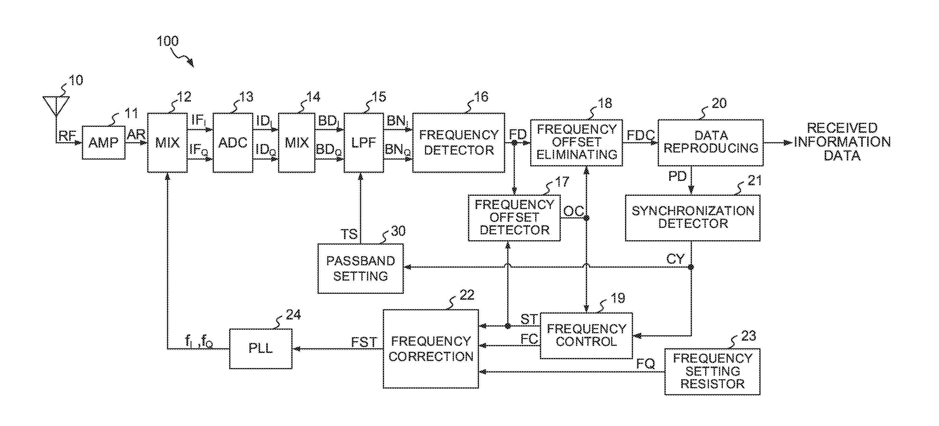
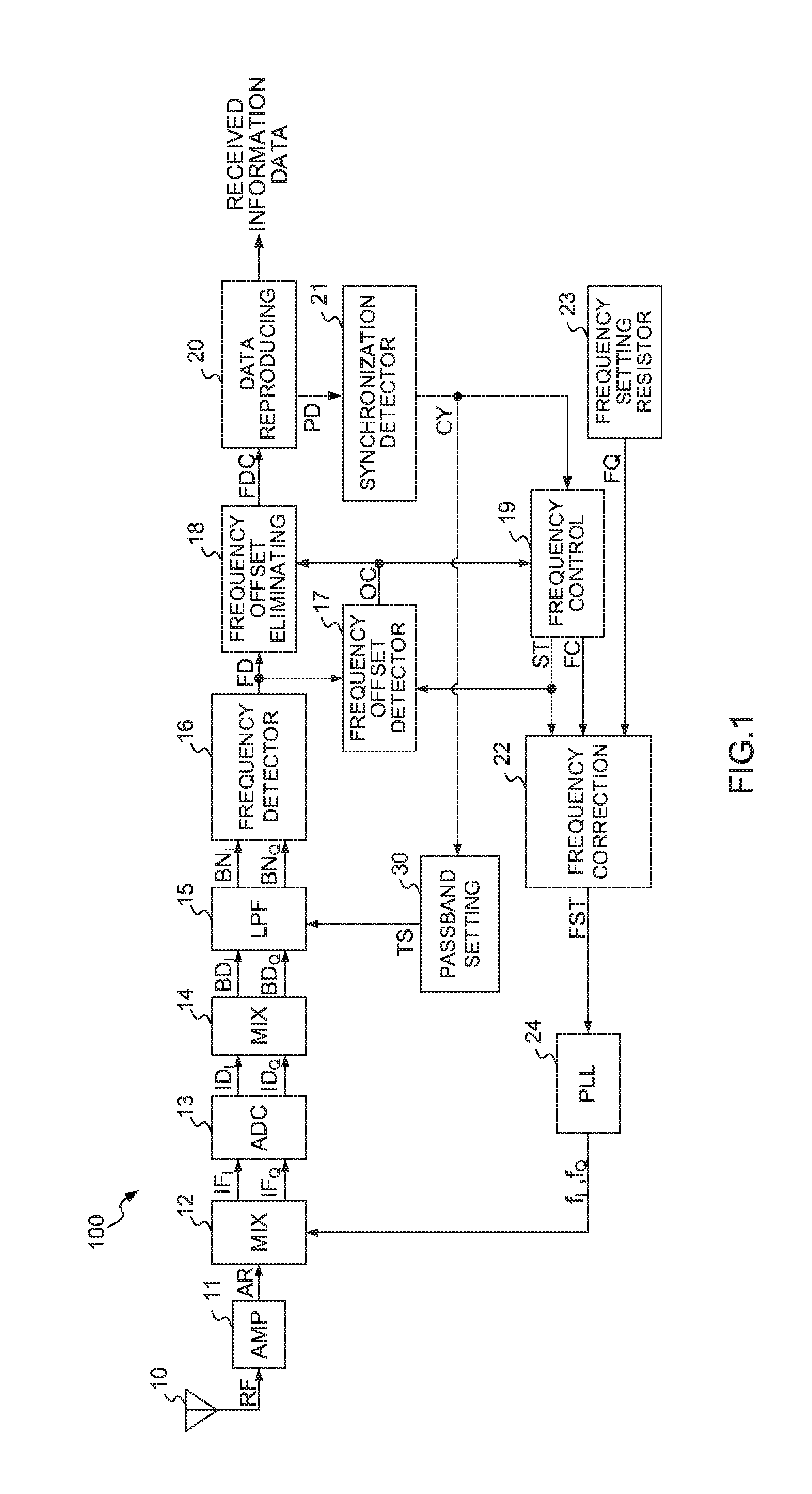
[0031]FIG. 1 is a block diagram showing an entire configuration of a receiving apparatus 100 according to the present invention.

[0032]An antenna 10 receives a wireless transmission wave which is transmitted from a transmission apparatus (not shown). The antenna 10 supplies an amplifier which may be a low noise amplifier with a high frequency signal RF on the basis of the wireless transmission wave as illustrated in FIG. 1. The wireless transmission wave is modulated in frequency in accordance with data sequences. Each frame of the data sequences comprises a preamble part consisting of a specific bit pattern representing a synchronization signal, a synchronization word representing a leading position of a user data piece, the user data pieces representing such information as audio, video and text. A digital modulation such as FSK is used as a modulation scheme in the modulation.

[0033]An amplifier 11 supplies a mixer 12 with a received signal AR obtained by amplifying the high frequen...


PUM


Abstract

An LPF eliminates noise components from baseband signal obtained by performing a frequency conversion on the received signal on the basis of the received wireless transmission wave. A passband setting part sets the upper limit of frequency of passband in the LPF at a high frequency while a synchronization signal is not detected and at a low frequency after a synchronization signal is detected.

Description

BACKGROUND OF THE INVENTION[0001]1. Field of the Invention[0002]The present invention relates to a receiving apparatus, in particular to a receiving apparatus for receiving and demodulating a wireless transmission wave, and to a receiving method for receiving the wireless transmission wave.[0003]2. Description of the Related Art[0004]A receiving apparatus has been proposed which employs a so-called FSK (Frequency Shift Keying) scheme as a digital modulation scheme used in a specified low power radio systems (For example, Japanese patent application Laid-Open No. H09-162936). Such receiving apparatus includes a mixer, a local oscillator, a filter such as a low-pass filter (referred to as “LPF” in the following description) and a demodulator. The mixer generates an intermediate frequency signal by mixing a received signal received by an antenna and a local oscillation signal generated in the local oscillator. The LPF eliminates noise components from the intermediate frequency signal. ...

Claims


Application Information

Patent Timeline
Patent Type & Authority Applications(United States)
IPC IPC(8): H04L27/152H04L27/26
CPCH04L27/1525H04L2027/0028H04L27/2655H04B1/26H04L27/0014H04L27/148H04L2027/003H04L7/033H04L27/16H04L27/38H04L2027/0053H04L2027/0065H04L7/042
Inventor HAFUKA, TAKAMITSU
Owner LAPIS SEMICON CO LTD
Why Eureka
Try Eureka