
Method of inducing porous structures in laser-deposited coatings

a technology of laser-deposited coatings and porous structures, which is applied in the field of material technology, can solve the problems of disadvantageous use of such layers in terms of complexity and cost of their production, and the limiting feature of heat resistance of modern gas turbine engines

Inactive Publication Date: 2016-07-28
SIEMENS ENERGY INC
View PDF27 Cites 25 Cited by
  • Summary
  • Abstract
  • Description
  • Claims
  • Application Information

AI Technical Summary

Benefits of technology

The patent text describes methods for coating gas turbine components with ceramic materials to increase their heat resistance. The methods involve using powdered materials in the presence of a gas-generating agent to create porous coatings with voids that reduce thermal conductivity and improve adhesion. The voids in the coatings can be formed using a gas-generating agent directed into a melted pool of the material. The resulting coatings have improved properties such as reduced thermal conductivity, increased adherence, and greater resistance to cracking, impact damage, and spalling. The methods can be used to increase the heat resistance of gas turbine components and improve the efficiency of gas turbine engines.

Problems solved by technology

Heat resistance is often the limiting feature in the performance of modern gas turbine engines.
Although bond coat materials such as MCrAlYs have proven effective as an intermediate layer to enhance adhesion and to accommodate differences in the thermal expansion between superalloy substrates and ceramic TBCs, the use of such layers is disadvantageous in terms of the complexity and cost of their production.
This is true, for example, because MCrAIY layers are often applied using expensive and complex processes such as vapor deposition and various spraying techniques.

Method used


Image

  • Method of inducing porous structures in laser-deposited coatings
  • Method of inducing porous structures in laser-deposited coatings
  • Method of inducing porous structures in laser-deposited coatings

Examples


Embodiment Construction

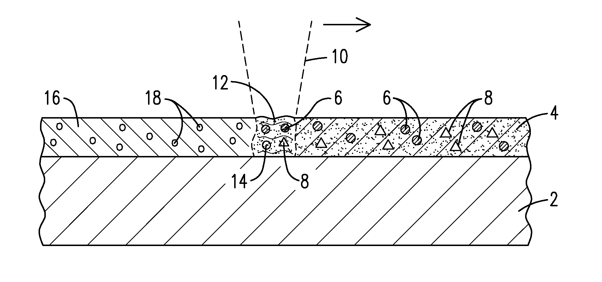
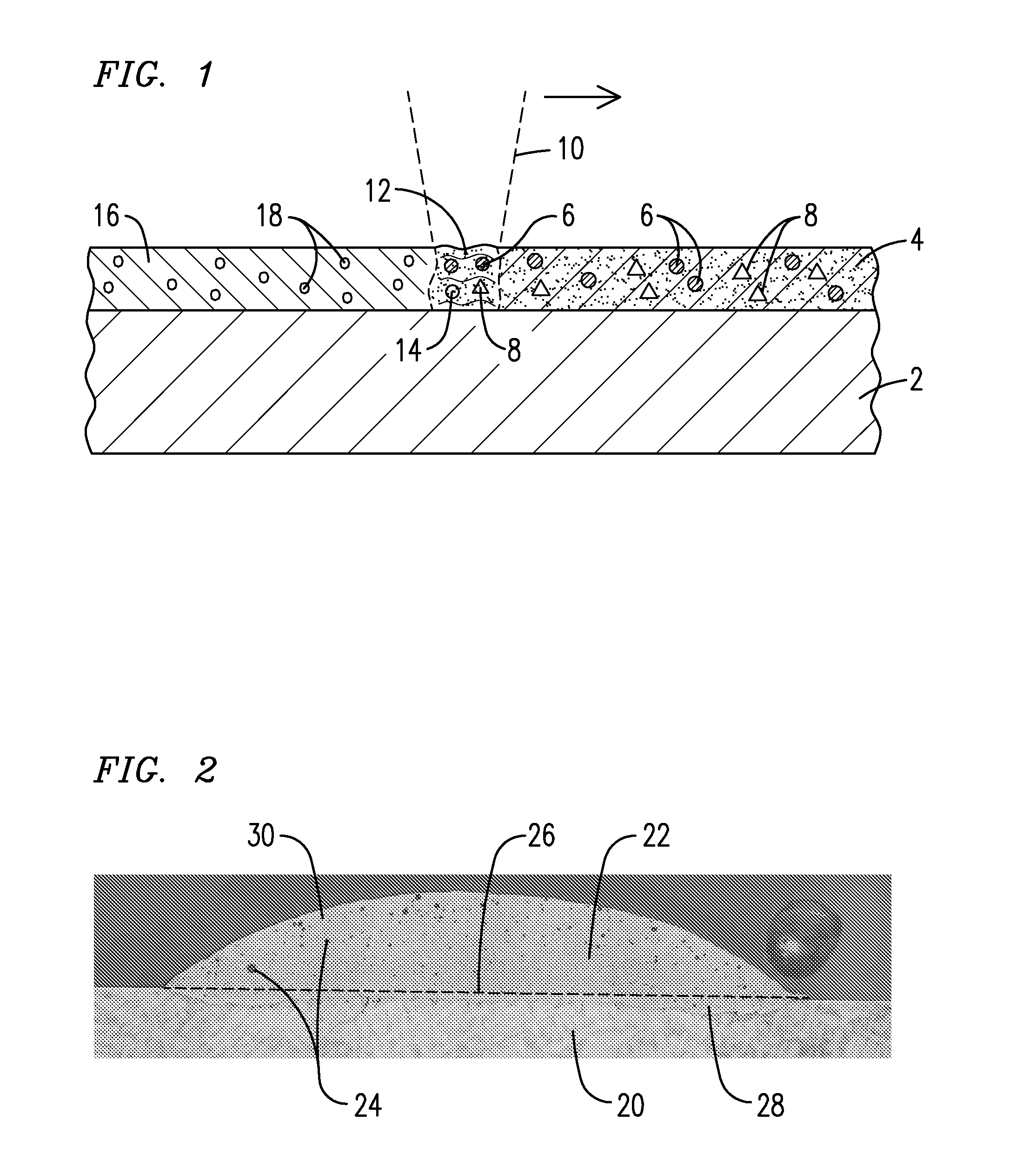
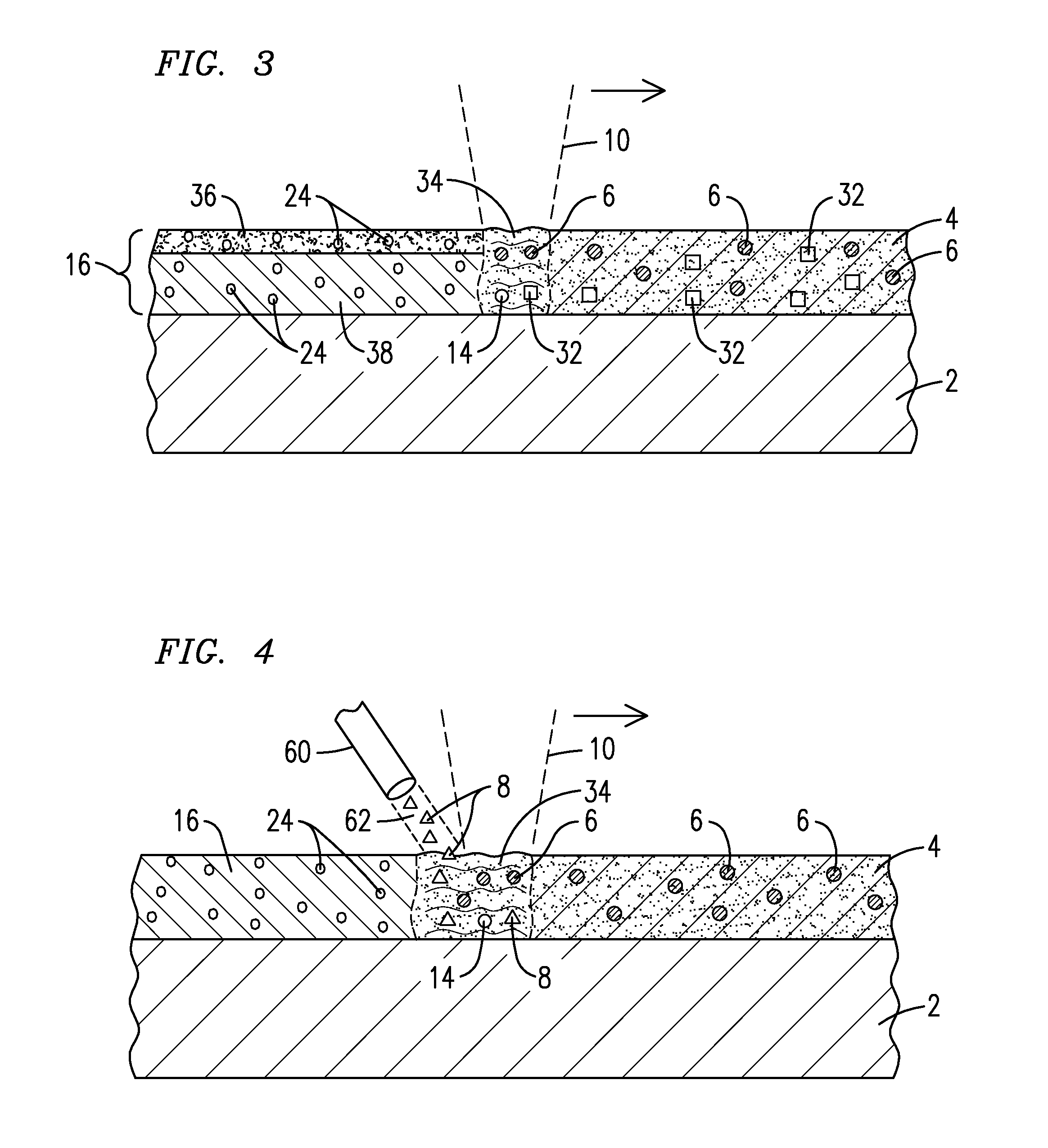
[0015]The present inventors have discovered methods for coating substrates, including superalloy substrates, with metallic and / or ceramic materials to produce porous (void-containing) coatings having improved properties such as reduced thermal conductivity, increased adherence, and greater resistance to cracking, impact damage and spalling. The present inventors have innovatively developed a combination of steps for manufacturing coated materials having improved thermo-protective properties as well as coated materials produced using simpler coating and bonding techniques amenable to a variety of high-temperature applications and applications requiring robust bonding between layers.

[0016]One embodiment of the present invention is a method involving the application of an energy beam to a powdered material in contact with a substrate, such that a gas-generating agent undergoes a chemical reaction to produce a gaseous substance that imparts voids (pores) to a resulting coating adhered t...


PUM

PropertyMeasurementUnit
Timeaaaaaaaaaa
Electrical resistanceaaaaaaaaaa
Mechanical propertiesaaaaaaaaaa

Abstract

A layer of a powdered material (4) is heated with an energy beam (10) such that at least one gas-generating agent (8) reacts to form at least one gaseous substance (14) to produce a void-containing coating (16) adhered to the surface of a substrate (2).The powdered material may contain a metallic material, a ceramic material, or both, and may also contain at least one of a flux material (32) containing the gas-generating agent and an exothermic agent (64). The heating may occur using a laser beam and may induce a melting or sintering of the powdered material to produce the void-containing coating. A gas turbine engine component exhibiting improved thermal and mechanical properties may be formed to include the void-containing coating, which may take the form of a bond coating, a thermal barrier coating, or both.

Description

[0001]This application is a continuation-in-part of U.S. patent application Ser. No. 14 / 274,952 filed on 12 May 2014 (attorney docket 2014P07212US), the entire contents of which are incorporated herein by reference.FIELD OF THE INVENTION[0002]This invention relates generally to the field of materials technology, and more specifically to methods of forming void-containing metal forms and components formed thereof.BACKGROUND OF THE INVENTION[0003]Thermal barrier coatings (TBCs) are utilized on hot section components of modern gas turbine engines, including the combustion and turbine section components, in order to protect the underlying base materials from high temperatures resulting from the flow of hot gases through the engine. These hot gases can be well above the melting point of the base materials which are typically superalloy materials. In the evolution of such technologies, there is an ongoing need to produce coatings having a low thermal conductivity (to impart heat resistanc...

Claims


Application Information

Patent Timeline
IPC IPC(8): B22F3/11B22F5/04B23K26/342B22F3/105C23C24/10C23C24/08
CPCB22F3/1125C23C24/103B22F5/04B23K26/342B22F3/1055C23C24/085C23C24/10C23C24/106B22F10/38B22F12/41B22F10/28B22F7/006B22F2999/00F01D5/288F05D2300/514F05D2300/6111Y02P10/25B22F3/105B22F2202/11
Inventor BRUCK, GERALD J.KAMEL, AHMED
Owner SIEMENS ENERGY INC
Learn More