
Implantable Electroacupuncture Device and Method

a technology of electroacupuncture and electrodes, applied in the field of implantable electroacupuncture devices and methods, can solve the problems of increasing difficulty, not focusing on acupuncture's efficacy as a medical procedure, and consuming a not insignificant portion of healthcare expenditure, so as to prevent the battery voltage, increase the battery voltage, and ensure the effect of acupuncture

Inactive Publication Date: 2016-07-21
VALENCIA TECH
View PDF8 Cites 3 Cited by
  • Summary
  • Abstract
  • Description
  • Claims
  • Application Information

AI Technical Summary

Benefits of technology

The invention is about a device that can be implanted in a person's body and powered only by a small battery. This device can generate stimulation pulses as directed by a prescribed regimen for up to two years. To achieve this, the device has a circuit that can limit the duration of the stimulation session to prevent the battery voltage from dropping below safe levels. The battery voltage is boosted using a converter circuit to ensure the device operates correctly and safely. Overall, this invention allows for a long-term, safe and effective way to stimulate the body with electroacupuncture therapy.

Problems solved by technology

Further, payment for acupuncture services consumes a not insignificant portion of healthcare expenditures in the U.S. and Europe.
There is general agreement that acupuncture is safe when administered by well-trained practitioners using sterile needles, but not on its efficacy as a medical procedure.
The problem lies in trying to ascertain what is fact from what is fiction.
This problem is made more difficult when conducting research on this topic because the insertion of needles, and the manipulation of the needles once inserted, is more of an art than a science, and results from such research become highly subjective.
The use of an outside coil, complex electronics, and the tubular shape of the microstimulator have all limited the commercial feasibility of the microstimulator device and applications described in the Whitehurst patents.
The methods and devices disclosed in these patents, however, typically utilize (i) large implantable stimulators having long leads that must be tunneled through tissue over an extended distance to reach the desired stimulation site, (ii) external devices that must interface with implanted electrodes via percutaneous leads or wires passing through the skin, or (iii) inefficient and power-consuming wireless transmission schemes.
Such devices and methods are still far too invasive, or are ineffective, and thus are subject to the same limitations and concerns, as are the previously described electrical stimulation devices.

Method used


Image

  • Implantable Electroacupuncture Device and Method
  • Implantable Electroacupuncture Device and Method
  • Implantable Electroacupuncture Device and Method

Examples


Embodiment Construction

Overview

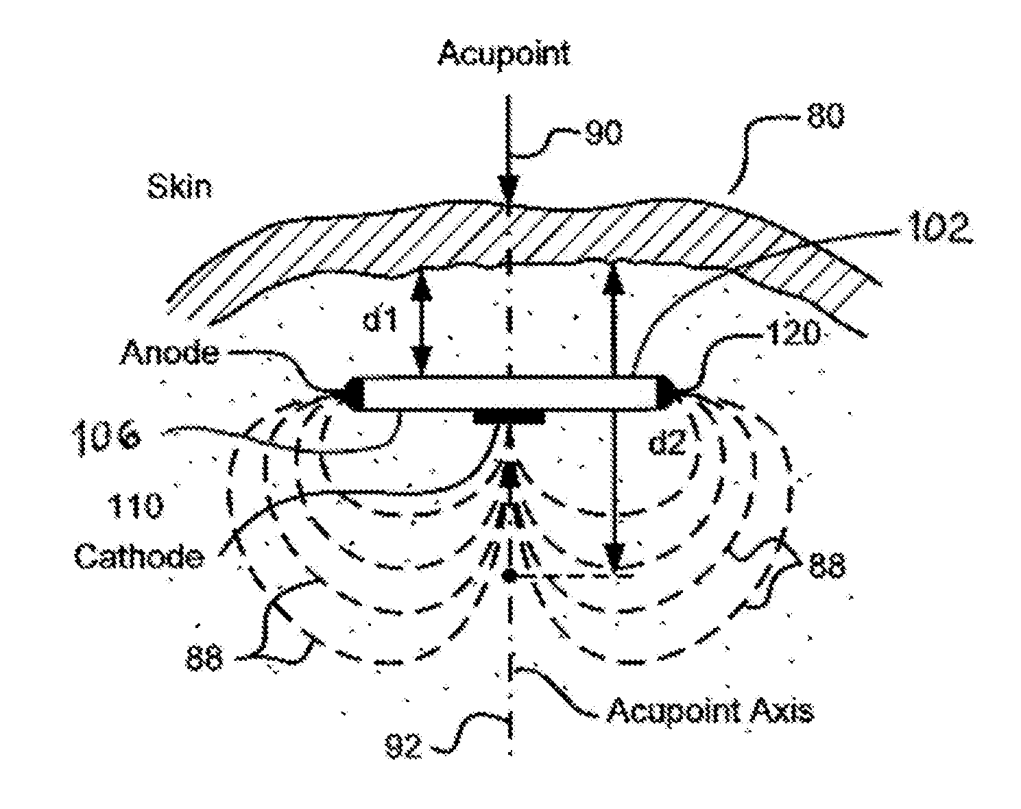
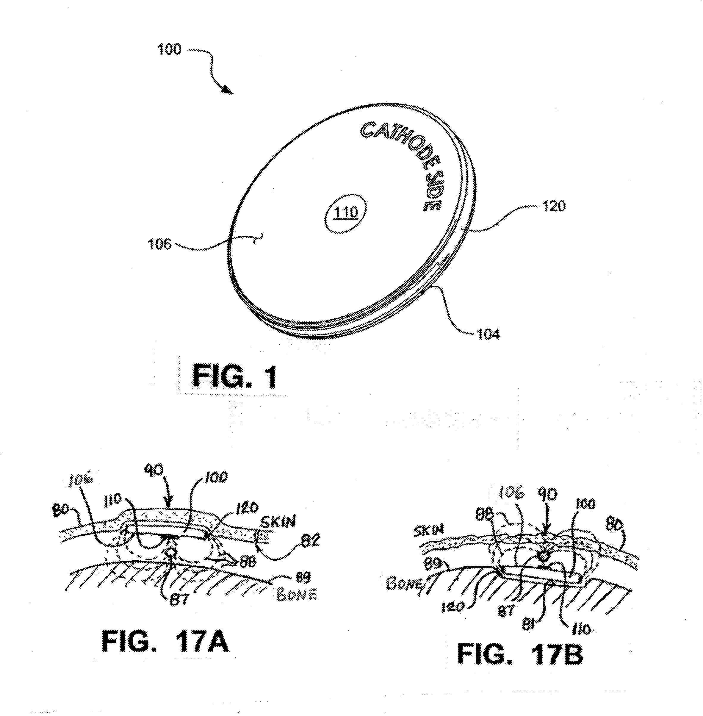
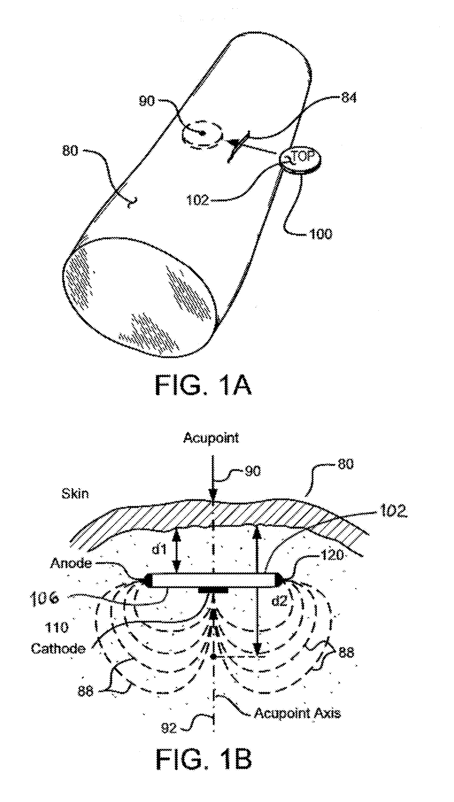
[0076]Disclosed and claimed herein is an implantable, self-contained, leadless electroacupuncture (EA) device having at least two electrode contacts mounted on the surface of its housing. The EA device disclosed herein, which is also referred to as an implantable electroacupuncture device (IEAD), is adapted to treat various medical conditions, deficiencies and illnesses of a patient when implanted at selected target tissue locations, e.g., acupoints, and when the IEAD is activated to provide EA stimulation at those target locations in accordance with a specified stimulation regimen. Ideally, the IEAD is coin-shaped and -sized, making it easy to implant.

[0077]In one preferred embodiment, the electrodes on the surface of the EA device include a central cathode electrode on a bottom side of the housing, and an annular anode electrode that surrounds the cathode. In another preferred embodiment, the annular anode electrode is a ring electrode placed around the perimeter edge of t...


PUM

PropertyMeasurementUnit
internal impedanceaaaaaaaaaa
output voltageaaaaaaaaaa

Abstract

An electroacupuncture device includes 1) a housing configured to be implanted beneath a skin surface of the patient at an acupoint within the patient, 2) a central electrode centrally located on a first surface of the housing, 3) an annular electrode that surrounds the central electrode on the first surface of the housing, the annular electrode being spaced apart from the central electrode, and 4) pulse generation circuitry located within the housing, wherein the pulse generation circuitry generates stimulation sessions at a duty cycle that is less than 0.05 and applies the stimulation sessions at the acupoint by way of the central electrode and the annular electrode in accordance with the duty cycle.

Description

RELATED APPLICATIONS[0001]The present application is a continuation application of U.S. patent application Ser. No. 13 / 796,314, filed Mar. 12, 2013, which application is a continuation-in-part (CIP) application of U.S. application Ser. No. 13 / 598,582, filed Aug. 29, 2012; U.S. patent application Ser. No. 13 / 622,653, filed Sep. 19, 2012; and U.S. patent application Ser. No. 13 / 630,522, filed Sep. 28, 2012. U.S. application Ser. No. 13 / 796,314 also claims priority under 35 U.S.C. §119(e) to U.S. Provisional Patent Application No. 61 / 609,875, filed Mar. 12, 2012; U.S. Provisional Patent Application No. 61 / 672,257, filed Jul. 16, 2012; U.S. Provisional Patent Application No. 61 / 672,661, filed Jul. 17, 2012; U.S. Provisional Patent Application No. 61 / 673,254, filed Jul. 19, 2012; U.S. Provisional Patent Application No. 61 / 674,691, filed Jul. 23, 2012; and U.S. Provisional Patent Application No. 61 / 676,275, filed Jul. 26, 2012. All of these applications are incorporated herein by referenc...

Claims


Application Information

Patent Timeline
Patent Type & Authority Applications(United States)
IPC IPC(8): A61H39/00A61N1/372A61N1/375A61N1/36
CPCA61H39/002A61N1/36067A61N1/36096A61N1/36107A61N1/36175A61N1/36117A61N1/37205A61N1/3756A61N1/36114A61N1/3758A61N1/36125A61N1/3782H01L2224/48091Y10T29/49002H01L2924/00014
Inventor GREINER, JEFFREY H.PETERSON, DAVID K. L.THENUWARA, CHULADATTAGREINER, STACY O.
Owner VALENCIA TECH
Learn More