Diesel exhaust system and method for controlling exhaust fluid dosing

a technology of exhaust system and exhaust fluid, which is applied in the direction of engines, mechanical equipment, machines/engines, etc., can solve the problems of pollutants passing through the scr system unreacted, diesel engines producing a significant amount of nitrogen oxides, and excess oxygen present in lean combustion to produce nitrogen oxides

Active Publication Date: 2016-07-07
ROBERT BOSCH CORP +1
View PDF0 Cites 6 Cited by
  • Summary
  • Abstract
  • Description
  • Claims
  • Application Information

AI Technical Summary

Benefits of technology

[0005]The invention provides, in yet another aspect, a method for controlling dosing of a diesel exhaust fluid within an exhaust system coupled to a diesel engine. A water condensation content of an exhaust aftertreatment device is analyzed with a controller based on one or more inputs to the controller. The controller verifies that the water condensation content within the exhaust aftertreatment device is below a specified water condensation threshold. A control signal is sent from the controller to a diesel exhaust fluid injection device to dose the exhaust aftertreatment device with the diesel exhaust fluid upon verification that the water condensation content within the exhaust aftertreatment device is below the specified water condensation threshold.

Problems solved by technology

However, the excess oxygen present within lean combustion produces nitrogen oxides.
Therefore, diesel engines produce a significant amount of nitrogen oxides amongst other various pollutants.
If the catalyst washcoat does not contain enough adsorbed ammonia, pollutants will pass through the SCR system unreacted.
If too much diesel exhaust fluid is injected, the ammonia passes through the SCR system unreacted.

Method used


Image

  • Diesel exhaust system and method for controlling exhaust fluid dosing
  • Diesel exhaust system and method for controlling exhaust fluid dosing
  • Diesel exhaust system and method for controlling exhaust fluid dosing

Examples


Embodiment Construction

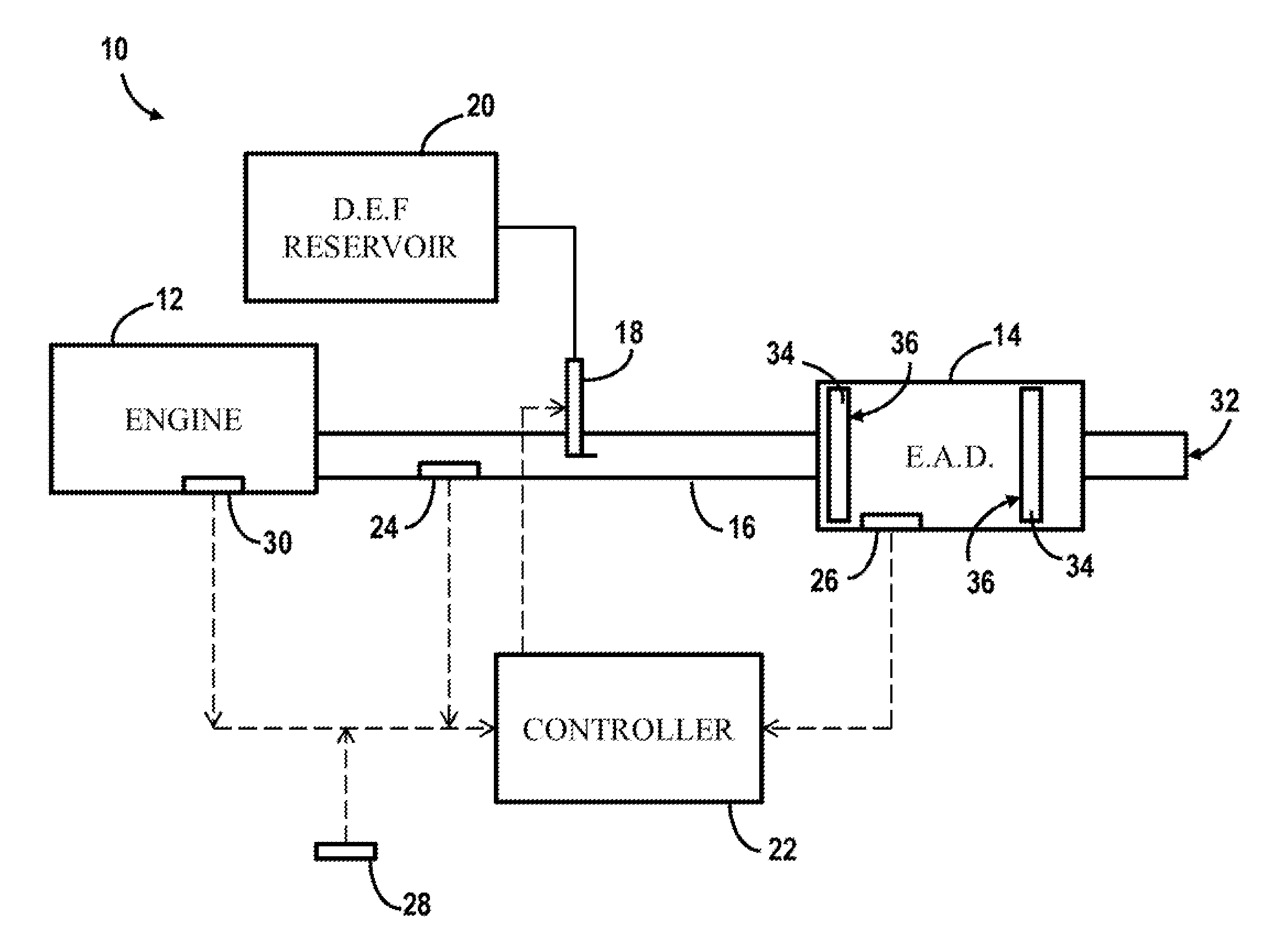
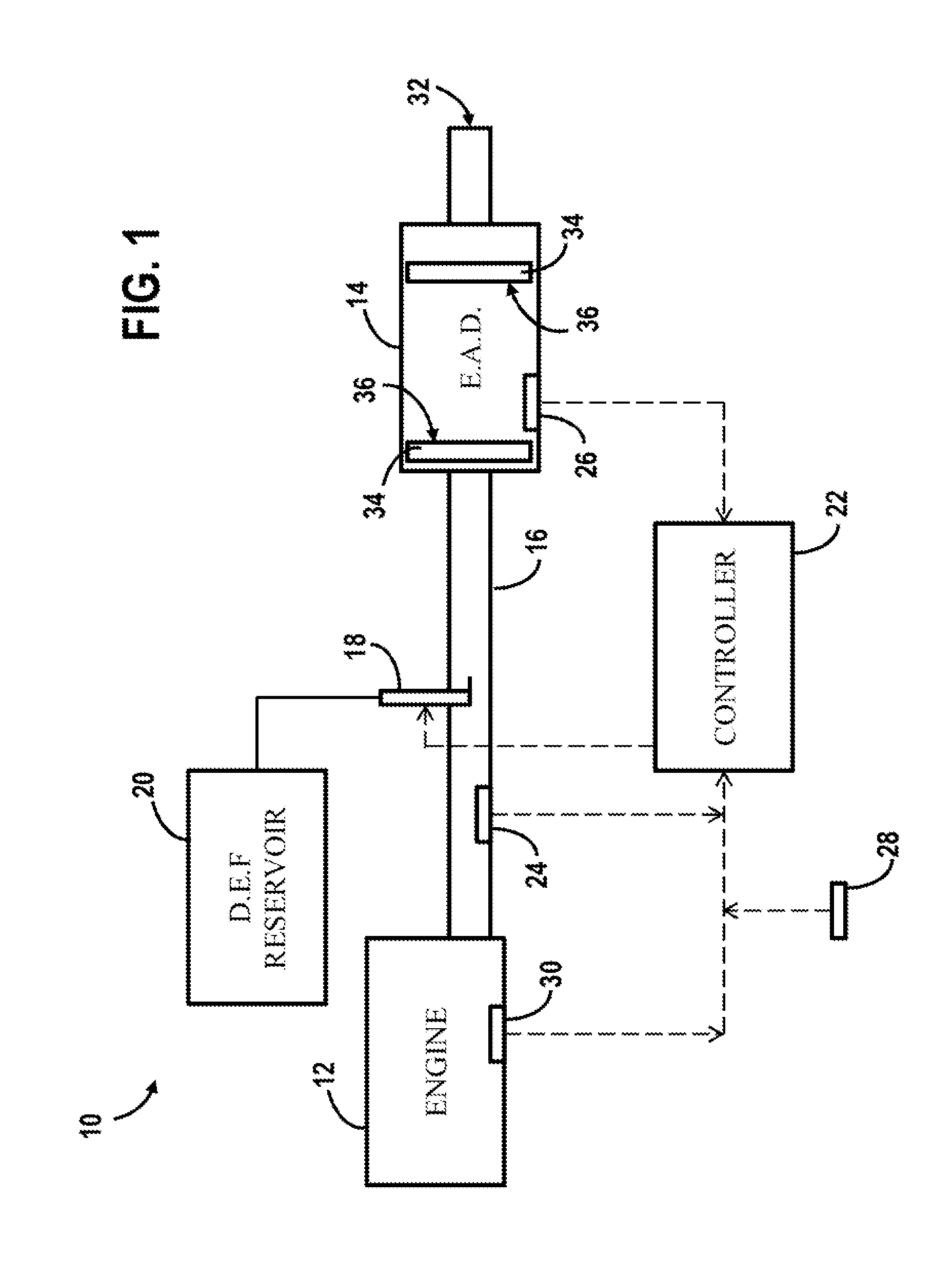
[0014]A diesel exhaust system 10, as shown in FIG. 1, is connected to a diesel engine 12. The engine 12 is connected to an exhaust conduit 16 defining an internal passage for receiving and guiding combustion reaction exhaust gases away from the engine 12 and out to the environment. The exhaust conduit 16 can include multiple exhaust pipe segments and extends from a first end at the engine 12 to a second end 32 where the exhaust is released into the environment. An exhaust aftertreatment device 14 is located within the diesel exhaust system 10 and can further define a portion of the conduit 16. The exhaust gas within the exhaust conduit 16 must pass through the exhaust aftertreatment device 14 before it is expelled into the environment. The exhaust aftertreatment device 14 can be embodied as a selective catalytic reduction (SCR) system comprising a substrate 34 for catalyst material. The exhaust aftertreatment device 14 may comprise multiple substrate sections 34, each having a surfa...


PUM


Abstract

A method for controlling dosing of a diesel exhaust fluid includes providing a diesel engine and an exhaust system. The exhaust system includes an exhaust aftertreatment device and is coupled to the diesel engine. An injection device is provided in the exhaust system for dosing the diesel exhaust fluid into the exhaust system according to a predetermined routine. A water condensation content of the exhaust aftertreatment device is determined. A dosing event, directed by the predetermined routine, is precluded so that the injection device is not operated to provide diesel exhaust fluid to the exhaust aftertreatment device when the water condensation content of the exhaust aftertreatment device is determined to be above a specified threshold value.

Description

BACKGROUND OF THE INVENTION[0001]In order to prevent the exhaust of unburned fuel, diesel engines can be run with a lean air-to-fuel ratio (greater than stoichiometric). However, the excess oxygen present within lean combustion produces nitrogen oxides. Therefore, diesel engines produce a significant amount of nitrogen oxides amongst other various pollutants. Government regulations require certain measures to be taken to limit the amount of pollutants that enter the atmosphere. This includes providing exhaust aftertreatment devices, such as selective catalytic reduction (SCR) systems, within the exhaust of many diesel vehicles.[0002]SCR systems contain a catalyst washcoat through which the exhaust of the diesel engine must pass. Periodically, a diesel exhaust fluid or reductant, such as urea, anhydrous ammonia, or aqueous ammonia is dosed in front of the catalyst. This fluid decomposes into ammonia and other gases, and the ammonia is adsorbed in the catalyst washcoat. As the exhaust...

Claims


Application Information

Patent Timeline
Patent Type & Authority Applications(United States)
IPC IPC(8): F01N3/28F01N3/20
CPCF01N3/2066F01N3/2896F01N3/208F01N9/00F01N2610/02F01N2900/08F01N2900/12F01N2900/1404F01N2900/1602F01N2610/146F01N2900/1628Y02T10/12Y02T10/40
Inventor KEPPY, BRENT D.CASARELLA, MARKMARENCO JIMENEZ, MARIA DOLORES
Owner ROBERT BOSCH CORP
Why Eureka
Try Eureka