Photoimageable compositions containing thermal base generators
- Summary
- Abstract
- Description
- Claims
- Application Information
AI Technical Summary
Benefits of technology
Problems solved by technology
Method used
Image
Examples
examples
[0179]The following abbreviations have been used hereinbefore and hereafter in describing some of the compounds, instruments and / or methods employed to illustrate certain of the embodiments of this invention:[0180]PENB—5-phenethylbicyclo[2.2.1]hept-2-ene; MA—maleic anhydride; TrisP-2-3,6-dicyclohexyl-7-(((6-diazo-5-oxo-5,6-dihydronaphthalen-1-yl)sulfonyl)oxy)-10-(2-hydroxyphenyl)-9,10-dihydroanthracen-2-yl 6-diazo-5-oxo-5,6-dihydronaphthalene-1-sulfonate; EPON 862—bis(4-(oxiran-2-ylmethoxy)phenyl)methane; Heloxy 84—triglycidyl ether of poly(oxypropylene)epoxide ether of glycerol; Si-75—((triethoxysilyl)propyl)disulfide; 3-GTS—triethoxy(3-(oxiran-2-ylmethoxy)propyl)silane, also commonly known as 3-glycidoxypropyl triethoxysilane; CXC 1761—a proprietary amidine salt; t-Boc imidazole—1-(tert-butoxycarbonyl)imidazole; 2-PHICN—1-(cyanoethyl)-2-phenyl-4,5-(dicyanoethoxymethyl)imidazole; EMI-24-CN—1-(2-cyanoethyl)-2-ethyl-4-methyl-imidazole; Irganox 1010—pentaerythritol tetrakis(3-(3,5-di-...
examples 1-4
[0184]A fully ring opened copolymer having the monomer composition of 50:50 molar ratio of PENB / MA ring opened with methanol (Mw 10,000, where R7 is hydrogen and R8 is methyl) (100 parts resin) was dissolved in PGMEA having the specific amounts of additives, expressed as parts per hundred resin (pphr) (TrisP-2 as the PAC (25 phr), Si-75 (3 phr) as adhesion promoter, 3-GTS (3 phr); EPON 862 (20 phr) and Heloxy 84 (30 phr) as crosslinking agents were mixed in an appropriately sized amber HDPE bottle with an appropriate amount of solvents. The mixture was rolled for 18 hours to produce a homogeneous solution. Particle contamination was removed by filtering the polymer solution through a 0.45 μm pore polytetrafluoroethylene (PTFE) disc filter under 35 psi pressure, the filtered polymer solution was collected in a low particle HDPE amber bottle and the resulting solution stored at 5° C.
[0185]To the above noted composition various TBGs as described hereinabove are added to see the effect ...
examples 5-7
[0189]The procedures of Examples 1 to 4 were substantially repeated in these Examples 5-7 except for using 3 phr of EMI-24-CN as TBG and further adding 5 phr of Irganox 1010 to the compositions. Three silicon wafers were spin coated with the composition and imaged in accordance with the procedures set forth in Examples 1-4. After developing the images the wafers were cured at three different temperatures: 140° C. for 1 hour (Example 5), 180° C. for 1 hour (Example 6), and 200° C. for 1 hour (Example 7).
[0190]The film thickness of each of the samples from Examples 5-7 was about 10 μm. The photo speed employed in each of these Examples 5-7 was about 405 mJ / cm2. The development time in each of these Examples 5-7 was about 65 seconds. The degree of film loss (DFL) was measured to be 11% in each of these Examples 5-7. The wafer stress was also measured in each of these Examples 5-7, which was about 14 MPa.
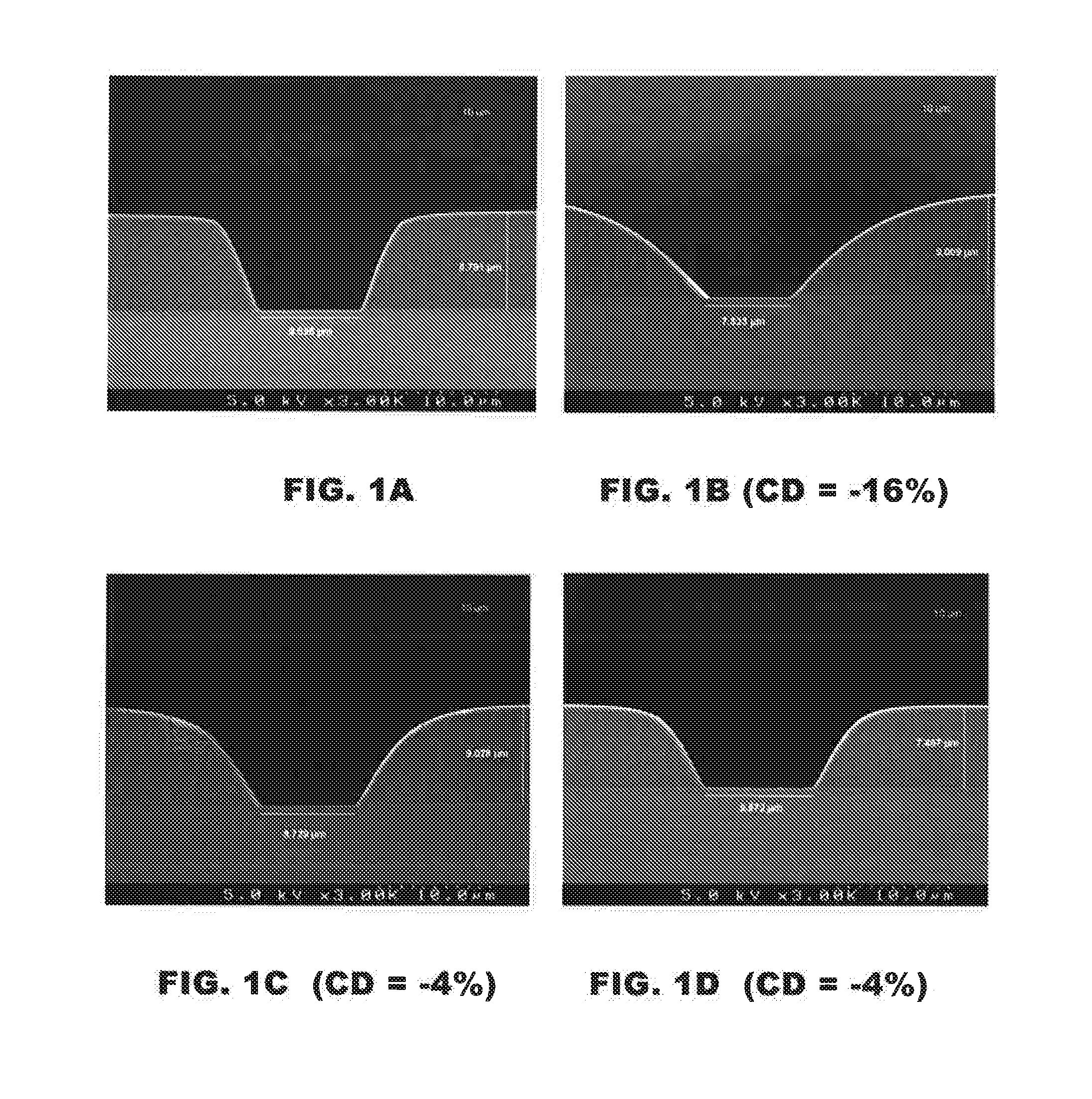
[0191]The pattern integrity of the developed films before and after cure was also e...
PUM
 Abstract
Description
Claims
Application Information
 - R&D
- Intellectual Property
- Life Sciences
- Materials
- Tech Scout
- Unparalleled Data Quality
- Higher Quality Content
- 60% Fewer Hallucinations
Browse by: Latest US Patents, China's latest patents, Technical Efficacy Thesaurus, Application Domain, Technology Topic, Popular Technical Reports.
© 2025 PatSnap. All rights reserved.Legal|Privacy policy|Modern Slavery Act Transparency Statement|Sitemap|About US| Contact US: help@patsnap.com


