Semiconductor Device and Electronic Device
a semiconductor and electronic technology, applied in the field of semiconductor devices, can solve the problems of increasing power consumption, image processing is executed while consuming a large quantity of power, etc., and achieve the effects of high speed, high resolution, and high-integration of semiconductor devices
- Summary
- Abstract
- Description
- Claims
- Application Information
AI Technical Summary
Benefits of technology
Problems solved by technology
Method used
Image
Examples
embodiment 1
[0096]In this embodiment, an imaging device that is one embodiment of the present invention is described with reference to drawings.
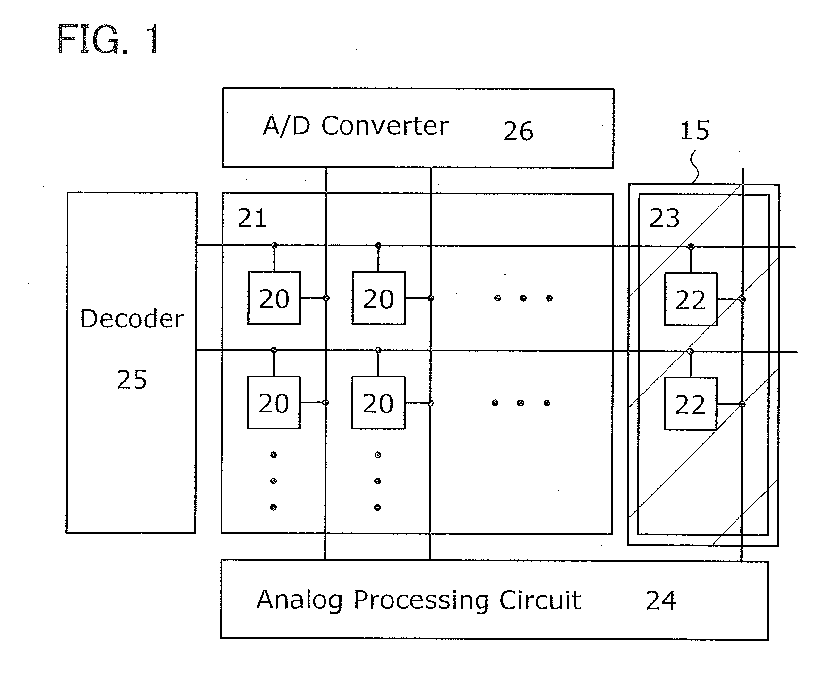
[0097]FIG. 1 is a block diagram illustrating an imaging device in one embodiment of the present invention. The imaging device includes a pixel array 21 where pixels 20 for imaging are arranged in a matrix, a reference pixel array 23 where reference pixels 22 for image processing are arranged, an analog processing circuit 24, and a row decoder 25 that outputs a potential for image processing to each pixel. Note that an A / D converter 26 can be used when image processing is not performed. Thus, the A / D converter 26 can be omitted.
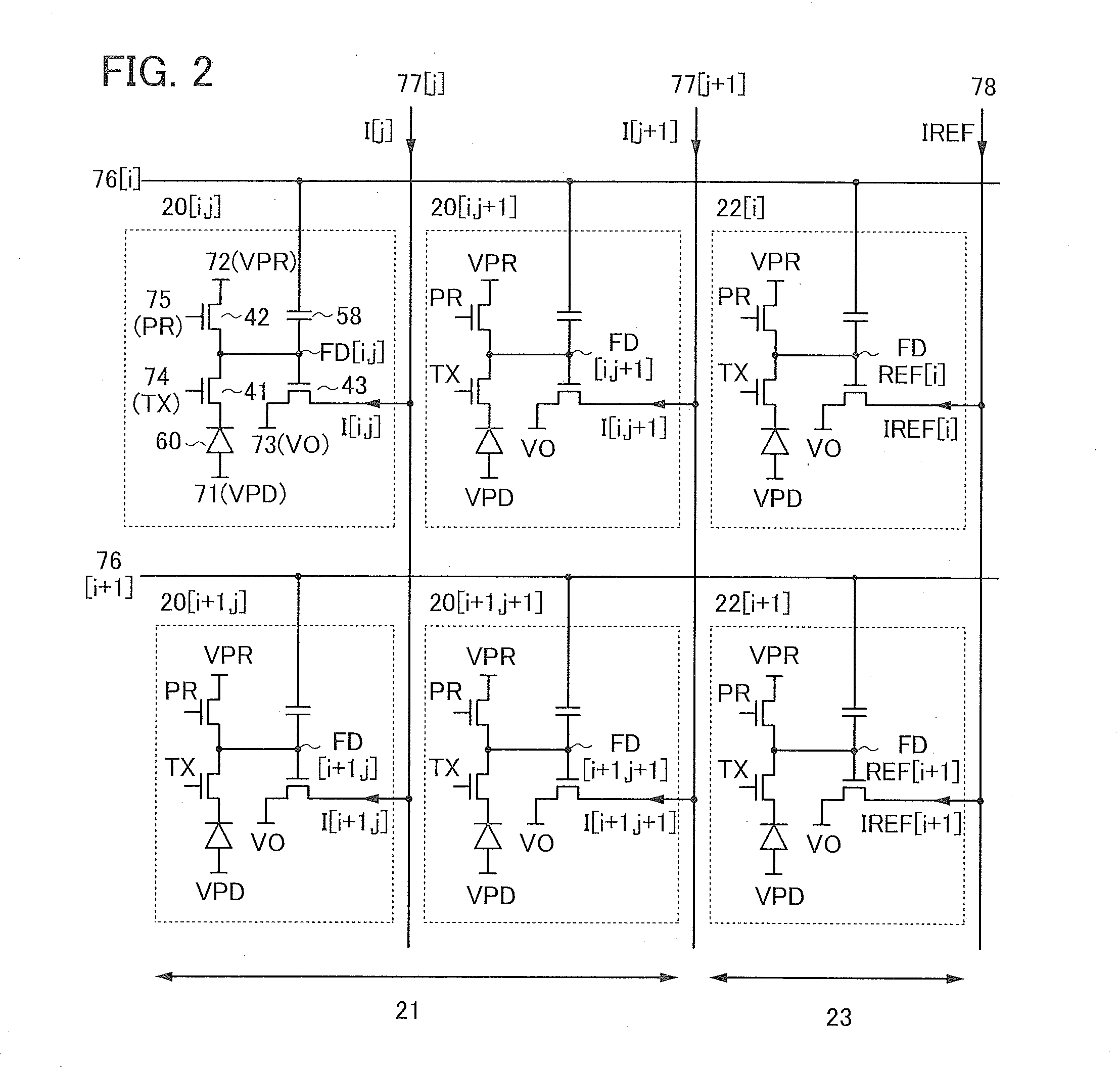
[0098]Although the pixel array 21 and the reference pixel array 23 are separately illustrated, circuits of the pixels 20 and the reference pixels 22 have the same structure. Therefore, in the plurality of pixels arranged in a matrix, the pixels in one column at an end function as the reference pixel array 23, and the other pixels ...
embodiment 2
[0228]In this embodiment, a semiconductor device including a memory element in one embodiment of the present invention is described with reference to drawings. The semiconductor device including a memory element in one embodiment of the present invention can perform vector matrix multiplication. The vector matrix multiplication is, for example, operation frequently used in an arithmetic processing unit, such as smoothing processing, edge enhancement processing, or cosine transform in image processing.
[0229]FIG. 25 is a block diagram illustrating a semiconductor device in one embodiment of the present invention. The semiconductor device includes a memory element array 521 where memory elements 520 are arranged in a matrix, a reference memory element array 523 where reference memory elements 522 for arithmetic processing are arranged, an analog processing circuit 524, and a row decoder 525 that outputs a potential for writing or reading to the memory element 520 and the reference memo...
embodiment 3
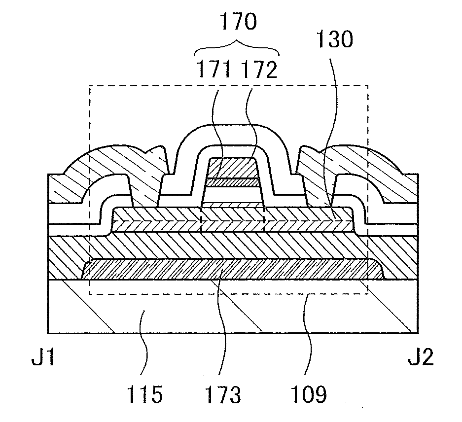
[0307]In this embodiment, a transistor including an oxide semiconductor that can be used in one embodiment of the present invention is described with reference to drawings. In the drawings in this embodiment, some components are enlarged, reduced in size, or omitted for easy understanding.
[0308]FIGS. 33A and 33B are a top view and a cross-sectional view illustrating a transistor 101 in one embodiment of the present invention. FIG. 33A is a top view, and a cross section in the direction of dashed-dotted line B1-B2 in FIG. 33A is illustrated in FIG. 33B. A cross section in the direction of dashed-dotted line B3-B4 in FIG. 33A is illustrated in FIG. 35A. The direction of dashed-dotted line B1-B2 is referred to as a channel length direction, and the direction of dashed-dotted line B3-B4 is referred to as a channel width direction.
[0309]The transistor 101 includes an insulating layer 120 in contact with a substrate 115; an oxide semiconductor layer 130 in contact with the insulating laye...
PUM
 Abstract
Description
Claims
Application Information
 - R&D
- Intellectual Property
- Life Sciences
- Materials
- Tech Scout
- Unparalleled Data Quality
- Higher Quality Content
- 60% Fewer Hallucinations
Browse by: Latest US Patents, China's latest patents, Technical Efficacy Thesaurus, Application Domain, Technology Topic, Popular Technical Reports.
© 2025 PatSnap. All rights reserved.Legal|Privacy policy|Modern Slavery Act Transparency Statement|Sitemap|About US| Contact US: help@patsnap.com


