Collector pipe for a heat exchanger device, a heat exchanger device and a method for emptying a heat exchanger device

a technology of heat exchanger and collector pipe, which is applied in the direction of heat exchange apparatus, stationary tubular conduit assembly, stationary conduit assembly, etc., can solve the problems of high material and processing costs, many tubes are required, and the degree of efficiency is normally associated with higher costs. , the effect of reducing the temperature differen

Inactive Publication Date: 2016-06-09
JAEGGI HYBRIDTECH
View PDF3 Cites 0 Cited by
  • Summary
  • Abstract
  • Description
  • Claims
  • Application Information

AI Technical Summary

Benefits of technology

The patent text explains that the efficiency of a heat exchanger is determined by the temperature difference between the fins and the tubes. When the fins and tubes have high conductivity and thickness, and the tubes are close to each other, the heat transfer is more effective and the efficiency is higher. However, this also means that using many tubes increases costs. The technical effect is to improve heat transfer efficiency while balancing cost with the degree of efficiency.

Problems solved by technology

However, many tubes also means higher costs of material and processing so that a higher degree of efficiency is normally associated with higher costs.
For an as high as possible degree of efficiency the tube spacing should be as small as possible which, however, leads to the problem that many tubes are required.
However, many tubes also means higher costs, since the tubes (generally made of copper) are considerably more expensive than the thin fins.
Moreover, a plurality of tubes, in particular having many windings and many arcs in many applications, for example as coolers in power plants, can have the effect that the heat exchanger apparatus cannot be completely emptied during the idle time which is, however, an essential requirement for an application in these fields.

Method used


Image

  • Collector pipe for a heat exchanger device, a heat exchanger device and a method for emptying a heat exchanger device
  • Collector pipe for a heat exchanger device, a heat exchanger device and a method for emptying a heat exchanger device
  • Collector pipe for a heat exchanger device, a heat exchanger device and a method for emptying a heat exchanger device

Examples


first embodiment

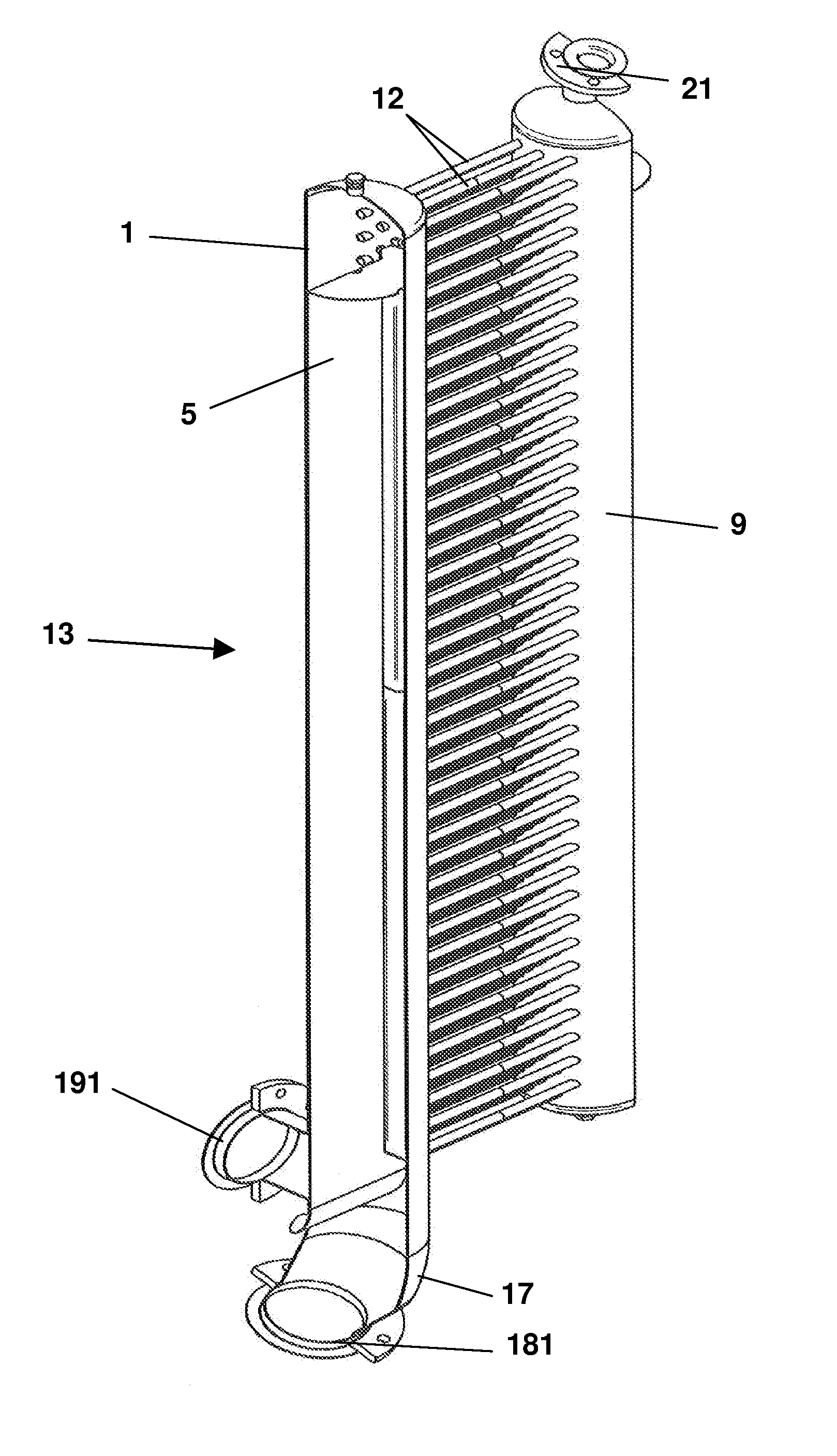
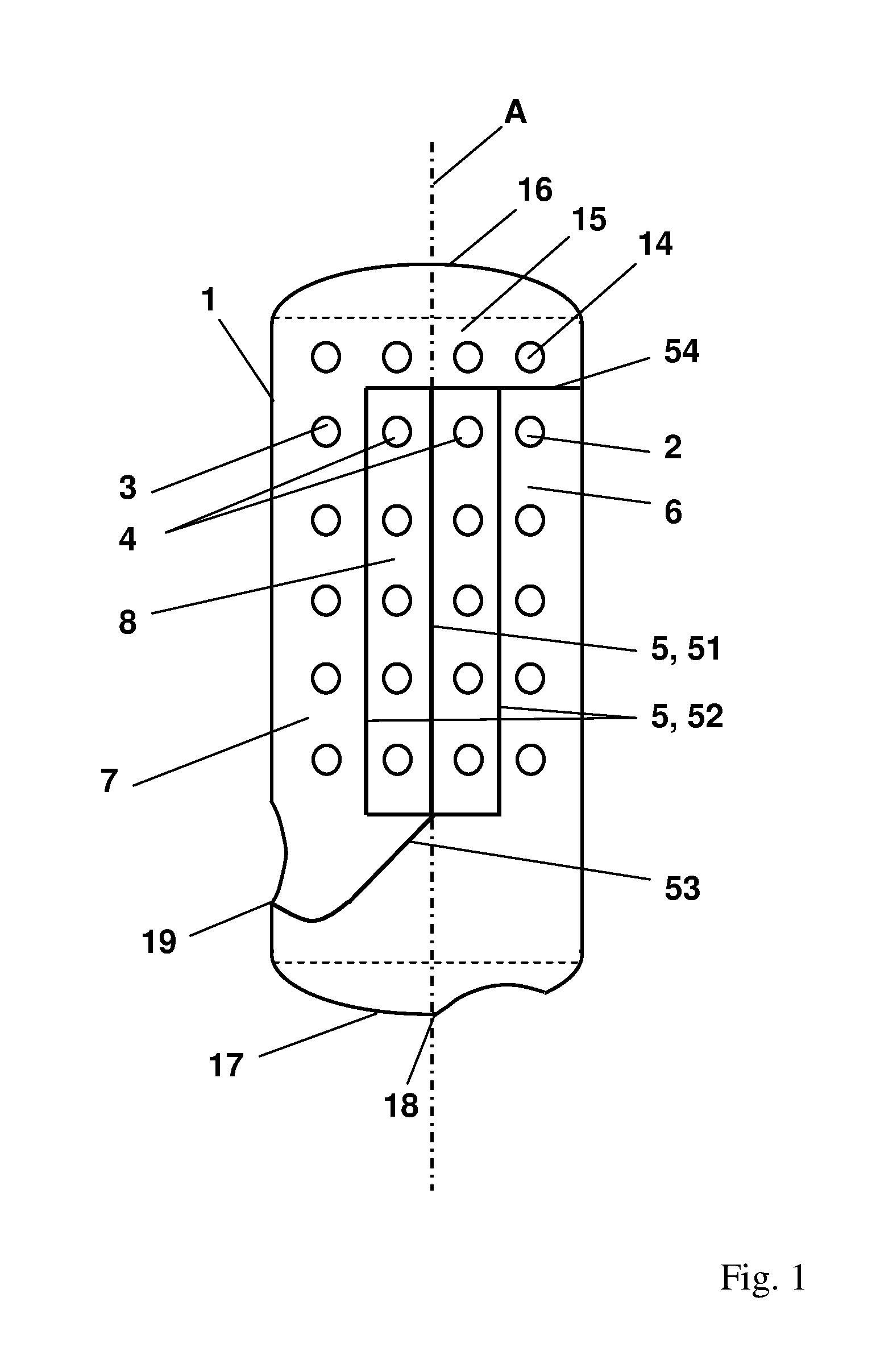
[0062]FIG. 1 shows a schematic illustration of the collection tube 1 in accordance with the invention. The collection tube 1 is configured as a generally hollow cylindrical tube, in particular as a hollow circular cylinder, which is open at a first and at a second axial end. The collection tube 1 comprises an outflow opening 2, an inflow opening 3 and a plurality of deflection openings 4. The outflow opening or the inflow opening or the deflection openings 2, 3, 4 are configured as an opening in a jacket surface of the collection tube 1. A plurality of outflow openings 2 are arranged vertically above one another, preferably having the same spacing at a first plane. Likewise a plurality of inflow openings or deflection openings 3, 4 are arranged vertically above one another, preferably having the same spacing, at a parallel first plane. The outflow opening or the inflow opening or the deflection openings 2, 3, 4 are horizontally arranged next to one another, preferably having the sam...

second embodiment

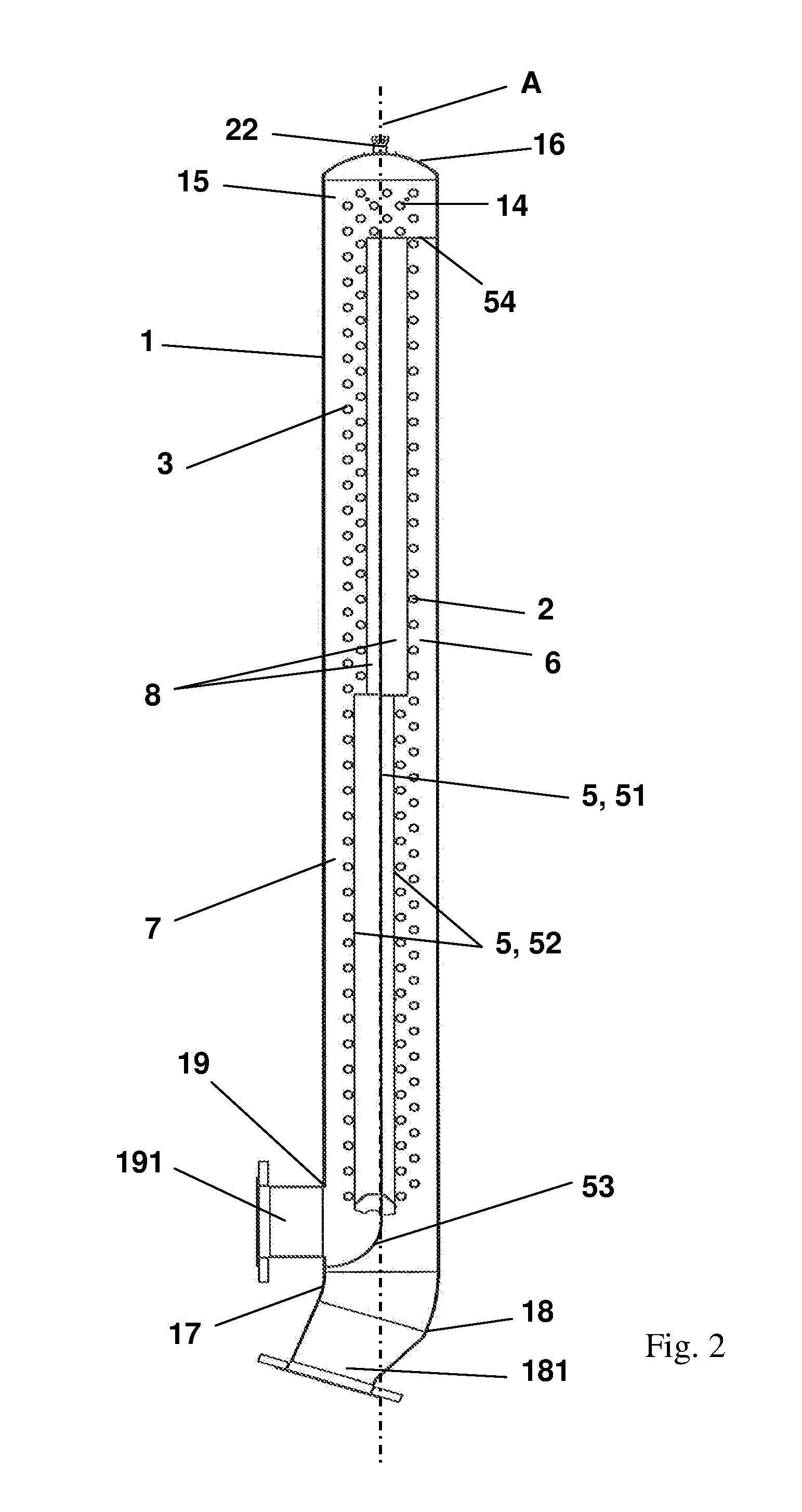
[0067]A schematic illustration of the collection tube 1 is illustrated in FIG. 2. The assembly of the collection tube 1 in this connection has many similarities to the collection tube 1 of FIG. 1, for which reason reference is only made to the differences. The first termination element 16 further comprises a compensation opening 22, wherein air flows into the collection tube for an open compensation opening 22. The separation element 5 is of two-part design, wherein the two parts of the separation element 5 are horizontally displaced with respect to one another so that the separation element 5 divides a like number of outflow openings, inflow openings and deflection openings 2, 3, 4 in a radial direction of the collection tube axis A. An inflow 191 is further arranged at the inflow opening 19 and an outflow 181 is further arranged at the outflow opening 18.

[0068]A schematic illustration of a first embodiment of a deflection tube is illustrated in FIG. 3. The deflection tube 9 is con...


PUM


Abstract

A collection tube for a heat exchanger apparatus includes an outflow opening, an inflow opening, a plurality of deflection openings, and a separation element. The separation element is configured and arranged in the collection tube to divide the collection tube into an outflow region in which the outflow opening is arranged, an inflow region in which the inflow opening is arranged, and a first deflection region in which the deflection openings are arranged, the separation element being arranged with respect to a collection tube axis such that the separation element encloses an angle with the collection tube axis, the collection tube axis extending in an axial longitudinal direction of the collection tube.

Description

CROSS-REFERENCE TO RELATED APPLICATIONS[0001]This application is a U.S. National Stage Application of International Application No. PCT / EP2014 / 063703, filed Jun. 27, 2014, which claims priority to European Application No. 13177985.2, filed Jul. 25, 2013, the contents of each of which is hereby incorporation herein by reference.BACKGROUND[0002]1. Field of Invention[0003]The invention relates to a collection tube for a heat exchanger apparatus, to a heat exchanger apparatus and to a method of emptying a heat exchanger apparatus.[0004]2. Background Information[0005]Heat exchanger apparatuses are found in a plurality of technical applications, for example, in cooling systems and cooling apparatuses for cooling rooms or for household fridges, in heating and air conditioning systems for houses, or for means of transport, such as, for example, cars, busses, ships and airplanes, or as coolers in power plants, combustion motors, computers or other installations producing heat. When used in p...

Claims


Application Information

Patent Timeline
Patent Type & Authority Applications(United States)
IPC IPC(8): F28D1/053
CPCF28D1/05308F28F9/0207F28D1/05325
Inventor BRENTROP, HANSJORGSCHAUB, TOBIAS
Owner JAEGGI HYBRIDTECH
Why Eureka
Try Eureka