
Resin composition for semiconductor encapsulation and semiconductor encapsulation method using same

a technology of resin composition and semiconductor encapsulation, which is applied in the direction of semiconductor devices, semiconductor/solid-state device details, solid-state devices, etc., can solve the problems of warpage, easy failure of filling, wire deformation, etc., and achieves small warpage and low viscosity

Inactive Publication Date: 2016-06-02
SHIN ETSU CHEM IND CO LTD
View PDF3 Cites 3 Cited by
  • Summary
  • Abstract
  • Description
  • Claims
  • Application Information

AI Technical Summary

Benefits of technology

The present invention provides a resin composition for semiconductor encapsulation that is fluid and has a low viscosity at room temperature. The composition has a high glass-transition temperature and is capable of restricting warp of the molded product during resin encapsulation. This resin composition is suitable for encapsulating various types of semiconductors and has excellent properties. A cured product of this composition has high thermal stability and is resistant to warp. The invention also provides a semiconductor encapsulation method that results in minimal warp after resin encapsulation molding.

Problems solved by technology

That is, in such case, there exists a concern that wire deformation may occur.
For these reasons, it is perceived as such that a filling failure will easily occur as an encapsulation area becomes large.
However, a warpage occurring after performing resin encapsulation molding is a significant problem in the case where a large area(s) are to be encapsulated at one time.
That is, in the case of a liquid epoxy resin composition to which a large amount of an inorganic filler has been added, wire sweep as a type of wire deformation and filling failures may occur easily, and resin supply is difficult at the time of production.

Method used


Image

  • Resin composition for semiconductor encapsulation and semiconductor encapsulation method using same
  • Resin composition for semiconductor encapsulation and semiconductor encapsulation method using same
  • Resin composition for semiconductor encapsulation and semiconductor encapsulation method using same

Examples


working example

[0066]The present invention is described in detail hereunder with reference to working and comparative examples. However, the present invention is not limited to the following working examples. Here, the notation “parts” in each example all refers to “parts by mass.” As for working examples 1 to 15, the resin compositions for semiconductor encapsulation were obtained by blending together the components shown in Table 1 at the ratios shown therein, and then using a triple roll mill to perform kneading in a homogenous manner. As for comparative examples 1 to 10, the resin compositions for semiconductor encapsulation were obtained by blending together the components shown in Table 2 at the ratios shown therein, and then using a triple roll mill to perform kneading in a homogenous manner. Particularly, the ingredients used in the working and comparative examples are as follows. In Table 1 and Table 2, the amounts of the ingredients are expressed as parts by mass.

Components Used

[0067](A)...


PUM

PropertyMeasurementUnit
glass-transition temperatureaaaaaaaaaa
temperatureaaaaaaaaaa

Abstract

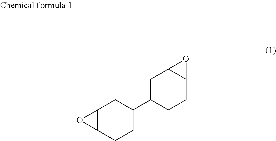
Provided are a resin composition for semiconductor encapsulation being fluid and exhibiting a low viscosity at a room temperature; and a semiconductor encapsulation method resulting in a small warpage even after performing molding through resin encapsulation i.e. a wafer level package-encapsulation method.The resin composition includes:(A) an alicyclic epoxy compound represented by formula 1:(B) an epoxy resin being liquid at a room temperature and an epoxy resin other than the alicyclic epoxy compound represented by formula 1;(C) an acid anhydride curing agent;(D) a curing accelerator; and(E) an inorganic filler, whereinthe component (A) is in an amount of 30 to 95 parts by mass with respect to 100 parts by mass of all the epoxy resins in the total amount of the resin composition, and the component (E) is contained in the total amount of the resin composition by 80 to 95% by mass.

Description

BACKGROUND OF THE INVENTION[0001]1. Field of the Invention[0002]The present invention relates to a resin composition for semiconductor encapsulation; and a semiconductor encapsulation method using the same.[0003]2. Background Art[0004]In recent years, significantly thin encapsulation resins have been used due to the fact that electronic parts have become smaller and thinner in the field of semiconductor packaging or the like. Conventionally, electronic parts such as semiconductors were encapsulated through transfer molding using solid epoxy resin compositions. However, it is required that the resin be able to flow to a narrow space(s) in the case where resin encapsulation is performed through transfer molding to obtain a thin package. That is, in such case, there exists a concern that wire deformation may occur. For these reasons, it is perceived as such that a filling failure will easily occur as an encapsulation area becomes large.[0005]Here, in recent years, compression molding u...

Claims


Application Information

Patent Timeline
Patent Type & Authority Applications(United States)
IPC IPC(8): C08L63/00H01L21/56
CPCH01L21/56C08L63/00C08G59/24C08G59/42H01L23/293H01L2924/0002C08K3/01H01L2924/00
Inventor KUSHIHARA, NAOYUKISUMITA, KAZUAKI
Owner SHIN ETSU CHEM IND CO LTD
Learn More