Driver circuit for an electro-absorption or micro-ring modulator and optical transmitter comprising such driver circuit

a technology of micro-ring modulator and driver circuit, which is applied in the direction of electromagnetic transmitters, optics, electromagnetic transmission, etc., can solve the problems of light intensity accumulation over multiples, distortion and degradation of the resulting frequency signal, and achieves reduced cost, higher density, and reduced cut-off frequency.

Active Publication Date: 2016-04-28
NVIDIA DENMARK APS
View PDF8 Cites 11 Cited by
  • Summary
  • Abstract
  • Description
  • Claims
  • Application Information

AI Technical Summary

Benefits of technology

[0013]Providing the voltage offset in one branch of the differential amplifier and using complementary outputs allows direct connection of the driver to the modulator without the use of a bias-T or other coupling components such as capacitors. The direct connection allows higher density, reduced cost, and a lower cut-off frequency—in fact zero—compared to known implementations. Also, by providing a built-in adjustable voltage offset, the adjustment of this does not affect the operating conditions of the entire IC, as would be the case in the driver of '596. By providing the driver voltage on two complementary driver outputs, and using the differential amplifier, then the voltage swing need only be half as big, which leads to an added advantage that the circuit elements may be selected smaller, have lower parasitic capacitances and thus be faster. Therefore, the driver circuit also needs half the power of the driver of '596 because the tail-current in the differential pair need only be half as big to provide the necessary voltage swing. Further, by providing the voltage offset in one differential branch, the supply voltage for the driver can be chosen without being dependent upon the bias of the modulator.

Problems solved by technology

When light of one or more selected resonant wavelengths of the modulator is passed through the MR modulator from an input waveguide, the light intensity builds up over multiple round-trips due to constructive interference.
Failing to couple this signal components onto the modulator will lead to distortion and degradation of the resulting frequency signal.

Method used


Image

  • Driver circuit for an electro-absorption or micro-ring modulator and optical transmitter comprising such driver circuit
  • Driver circuit for an electro-absorption or micro-ring modulator and optical transmitter comprising such driver circuit
  • Driver circuit for an electro-absorption or micro-ring modulator and optical transmitter comprising such driver circuit

Examples


Embodiment Construction

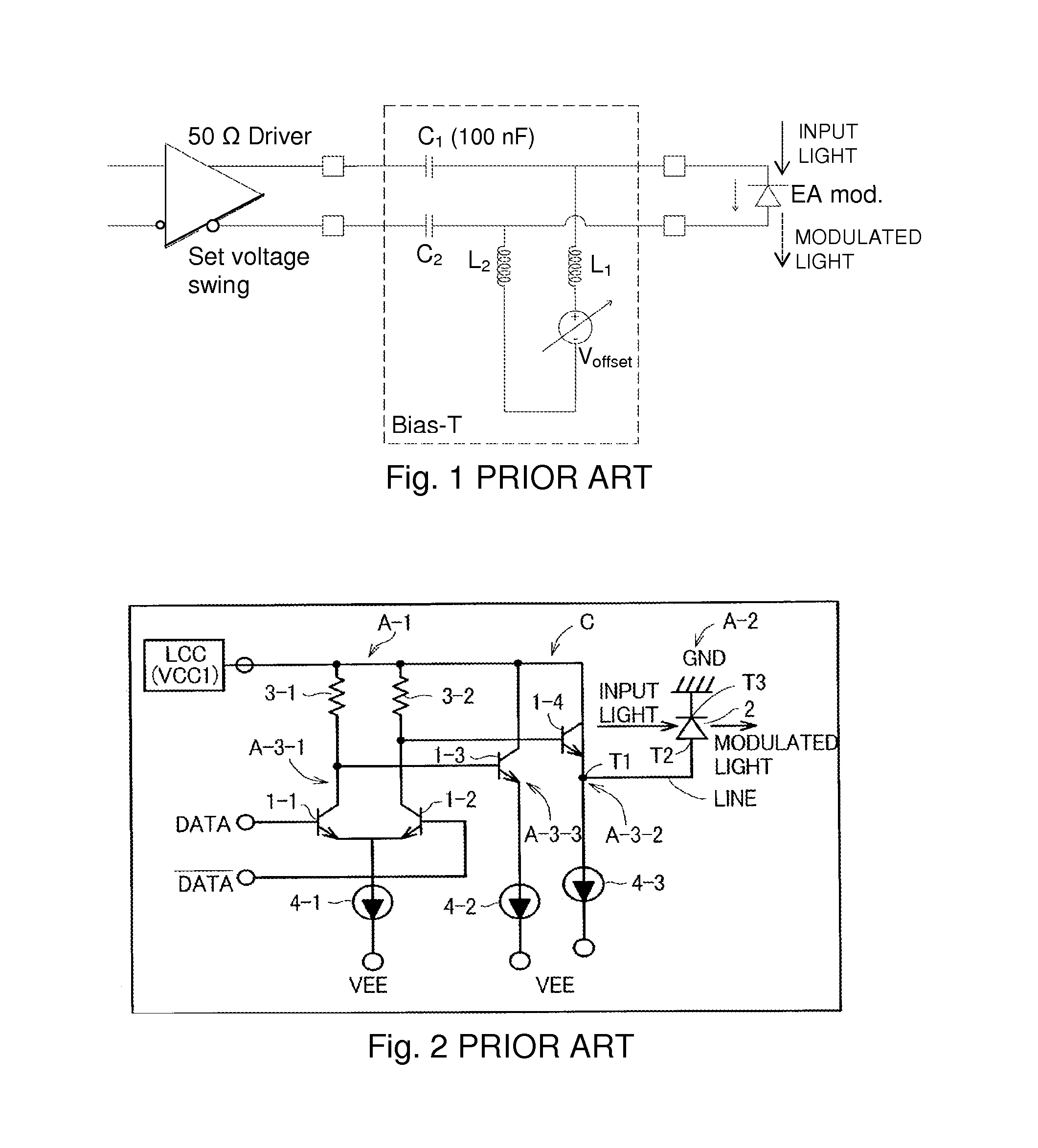
[0023]FIG. 2 from U.S. Pat. No. 7,099,596 shows a known example of a driver circuit using a differential pair for providing drive voltage to complementary outputs in an optical transmitter C comprising a voltage generating circuit LCC for applying a desired voltage to a common collector terminal of a differential amplifier A-3-1. The voltage VCC1 applied to the common collector terminal by the voltage generating circuit LCC is variable for adjustment of the applied voltage between the common collector terminal and VEE. The capacitance between output terminal T1 of the emitter follower circuits A-3-2 and the voltage input terminal T2 of the optical modulator 2 is not increased hereby. This is an improvement relative to the bias-T setup, and still retains the adjustable drive voltage. However, by adjusting the voltage VCC1 the entire circuit is affected and must be re-considered.

[0024]Relative to the bias-T, in order to achieve the same modulation current with a single-ended drive as ...


PUM


Abstract

A modulator driver circuit for providing a drive voltage to an electro-absorption modulator, such a Franz-Keldysh modulator, or to a micro-ring modulator, and an optical transmitter comprising such driver circuit, where said driver circuit comprises a differential amplifier and at least one differential branch of the differential amplifier being provided with a voltage offset. This provide for a bias voltage being adjustable within the driver circuit itself. Preferably, said differential amplifier is arranged for supplying drive voltage to two complementary driver outputs providing a reverse bias relative to the modulator. In one embodiment, said differential amplifier comprises a cascode in the differential branch not being provided with the voltage offset.

Description

BACKGROUND OF THE INVENTION[0001]This invention relates generally to an optoelectronic modulator driver circuit, and more specifically to driver circuits for controlling and powering electro-absorption or micro-ring modulators; as well it relates to an optical transmitter comprising such driver circuit.[0002]High speed optical transmission networks in the area of around 25-50 Gb / s often rely on the modulation of light in order to transmit data. Lasers are often used as the light source for this light data. Rather than modulating the laser itself directly a separate modulator is sometimes used. The laser is operated in continuous wave mode and the laser light is then passed into a light modulator. The modulator varies the amount or intensity of the laser light passed through it.[0003]One such type of modulator is the electro-absorption (EA) modulator, another more recently discussed modulator type is the micro-ring modulator.[0004]The EA modulator takes a generally laser diode light ...

Claims


Application Information

Patent Timeline
Patent Type & Authority Applications(United States)
IPC IPC(8): H04B10/564H04B10/516
CPCH04B10/516H04B10/564G02F1/0121G02F1/0155G02F1/0157H04B10/505
Inventor CHRISTENSEN, STEEN BAK
Owner NVIDIA DENMARK APS
Why Eureka
Try Eureka