Grey cast iron-doped diamond-like carbon coatings and methods for depositing same
- Summary
- Abstract
- Description
- Claims
- Application Information
AI Technical Summary
Benefits of technology
Problems solved by technology
Method used
Image
Examples
example 1
“Lowly-Doped” GCI-Doped DLC Coating
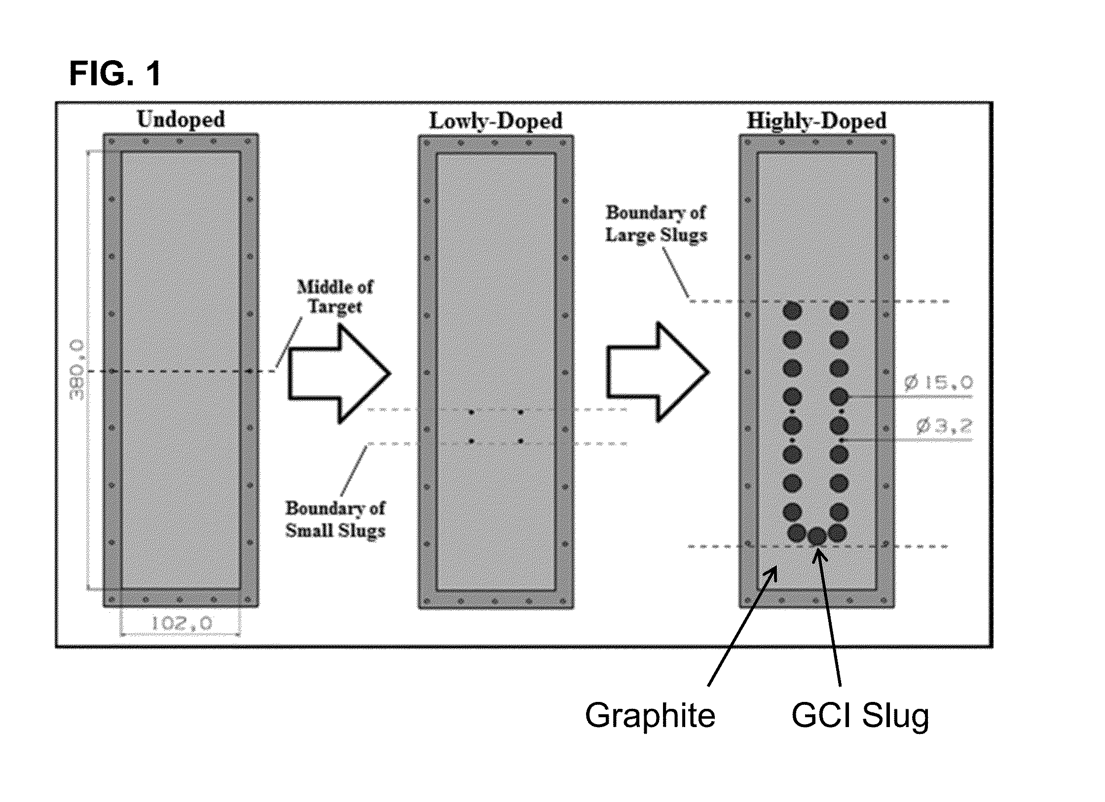
[0081]Cylindrical slugs were sheared from a GCI rod and polished to a surface roughness of about 1 μm. The slugs were lathed to a diameter of 3.2 mm and a height of about 0.25 cm. Four slugs were press-fit into a graphitic target such that the polished surface of the slug was flush with the surface of the graphite, in locations according to FIG. 1, “Lowly-Doped.”
[0082]Following modification, the composite target and was loaded into a dual-target magnetron physical vapor sputtering chamber. Target conditioning was performed according to the following steps:[0083]A. The unloaded substrate holder was introduced into the deposition chamber and rotated at 10.5 rpm.[0084]B. Ar gas was fed into the chamber at 100.0 sccm and stabilized.[0085]C. 0.1 kW of power was applied to the graphite target for ≈600 s. Target voltage and number of arc events were recorded in situ.[0086]D. If the target voltage stabilized, then 0.2 kW of power was applied to the graphit...
example 2
“Highly-Doped” GCI-Doped DLC Coating
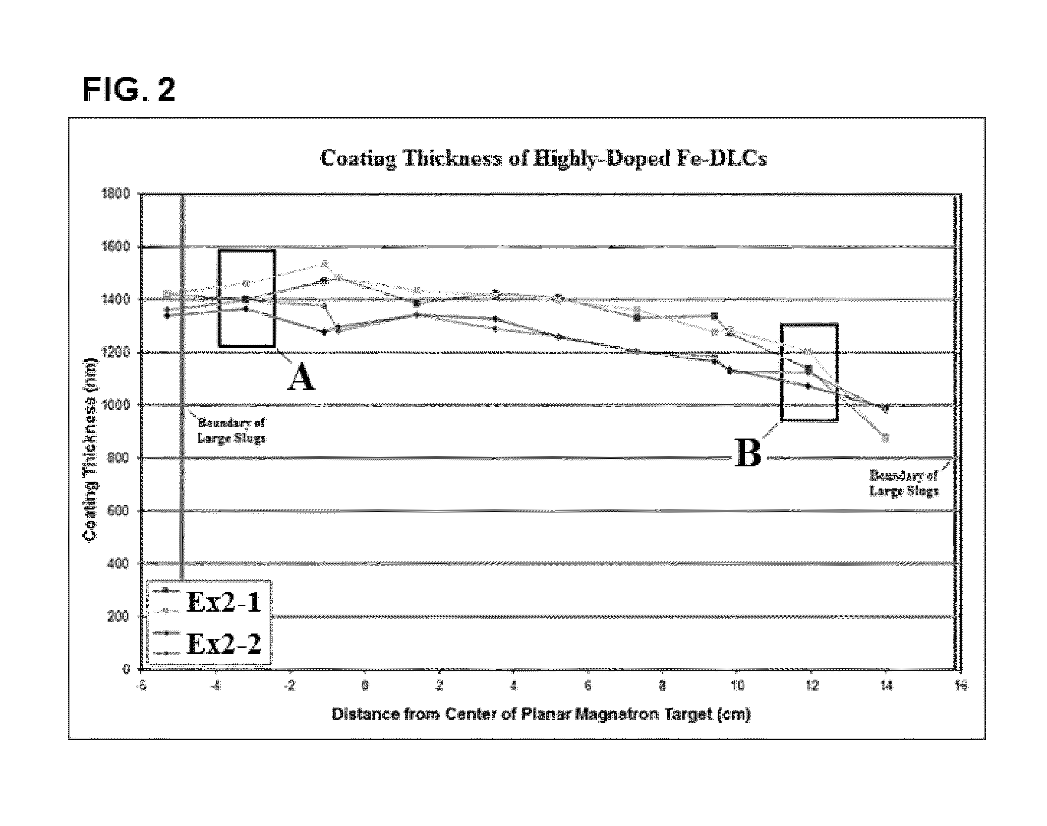
[0105]Cylindrical slugs were sheared from a GCI rod and polished to a surface roughness of about 1 μm. The slugs were lathed to a diameter of 15 mm and a height of about 0.25 cm. Nineteen slugs were press-fit into the graphitic target of Example 1 graphitic target such that the polished surface of the slug was flush with the surface of the graphite, in locations according to FIG. 1, “Highly-Doped.” The four 3.2 mm slugs press-fit into the target in Example 1 remained in place.
[0106]Following modification, the composite target was loaded into a dual-target magnetron physical vapor sputtering chamber. Coupled target conditioning and cleaning was performed according to the following steps:[0107]A. The unloaded substrate holder was introduced into the deposition chamber and rotated at 10.5 rpm.[0108]B. Ar gas and N2 gas were fed into the chamber at 50.0 sccm each and stabilized.[0109]C. 0.1 kW of power was applied to the graphite target for ≈600 s. Ta...
example 3
“Highly-Doped” GCI-Doped DLC Coating
[0137]Steps A-Y were carried out according to Example 2. In this case, a 52100 steel ball substrate was loaded in step N.
[0138]Two coatings were deposited according to Example 2, with the following parameters:
TABLE 5AFEX2PEX3SBEX3TEX3Coating(sccm)(kW)(V)(S)Ex 3-111−5012600Ex 3-281−507950
[0139]The 52100 steel ball substrates were positioned in the substrate holder such that four samples could be collected in which the coating compositions were essentially identical to those measured in Example 2.
TABLE 6Non-C Elemental Ti InterlayerFe CompositionThicknessCoating(at. %)(at. %)(nm)Ex 3-1A282.5% Ar1501.0% SiTrace Mn, CuEx 3-1B352.2% Ar1001.3% SiTrace Mn, CuEx 3-2A122.0% Ar1500.5% SiTrace Mn, CuEx 3-2B131.7% Ar1000.7% SiTrace Mn, Cu
PUM
| Property | Measurement | Unit |
|---|---|---|
| Composition | aaaaa | aaaaa |
| Concentration | aaaaa | aaaaa |
| Content | aaaaa | aaaaa |
Abstract
Description
Claims
Application Information
 - R&D
- Intellectual Property
- Life Sciences
- Materials
- Tech Scout
- Unparalleled Data Quality
- Higher Quality Content
- 60% Fewer Hallucinations
Browse by: Latest US Patents, China's latest patents, Technical Efficacy Thesaurus, Application Domain, Technology Topic, Popular Technical Reports.
© 2025 PatSnap. All rights reserved.Legal|Privacy policy|Modern Slavery Act Transparency Statement|Sitemap|About US| Contact US: help@patsnap.com


