
Method for producing micro- or nanostructures in polymeric film materials

a polymeric film and nano-structure technology, applied in the direction of filament/thread forming, other domestic articles, optical articles, etc., can solve the problems of high nip pressure, shorten the life of metallic shims, and too narrow web widths required for continuous roll-to-roll mass production of flexible films, etc., to achieve easy manufacturing and handling of large polymeric master films, and large-scale mass production

Inactive Publication Date: 2016-04-21
ISCENT OY
View PDF0 Cites 22 Cited by
  • Summary
  • Abstract
  • Description
  • Claims
  • Application Information

AI Technical Summary

Benefits of technology

This patent is about a method and a master film that can be used to create polymer films with micro- or nanostructures on their surface. The master film is made by coating a polymer film with a coating layer that helps to improve the properties of the film. The coating layer can contain fillers like abrasion resistant materials, lubricants, and release agents. The master film is easier to handle and can be used in continuous processing. The method and the master film can be used to create products with additional patterns or effects that show the authenticity of the product. The polymer films made using this method are affordable and safe for the environment.

Problems solved by technology

Although industrial manufacturing of diffractive optical elements is comparatively simple, their manufacturing requires machines using high nip pressures.
The high nip pressures used in the manufacturing process shortens the life time of metallic shims.
Another challenge is too narrow web widths required for continuous roll-to-roll mass production of flexible films, which is due to very high demand for mechanical performances of the shim assembly, and nip pressures.
The disadvantage of the method above is that industrial scale extrusion processes require larger metallic shims to be assembled around cooling rollers.
Large metallic shims are not available and the manufacturing of large metallic shims by embossing techniques is difficult and very costly.

Method used


Image

  • Method for producing micro- or nanostructures in polymeric film materials
  • Method for producing micro- or nanostructures in polymeric film materials
  • Method for producing micro- or nanostructures in polymeric film materials

Examples


example 1

[0058]Extrusion coating of PE (polyethylene, extrusion coating grade, Borealis CA7230) onto carton board (Ensocoat grammage 190 g / m2).

Parameters used in extrusion coating:[0059]web and die width 400 mm[0060]PE coating weigth 35 g / m2[0061]melting temperature 250-300° C.[0062]cooling roller diameter 600 mm, temperature 15° C.[0063]nip pressure between cooling roller and rubber pressure roller 3.0-5.0 bar[0064]line speed 50, 60, 80 m / min

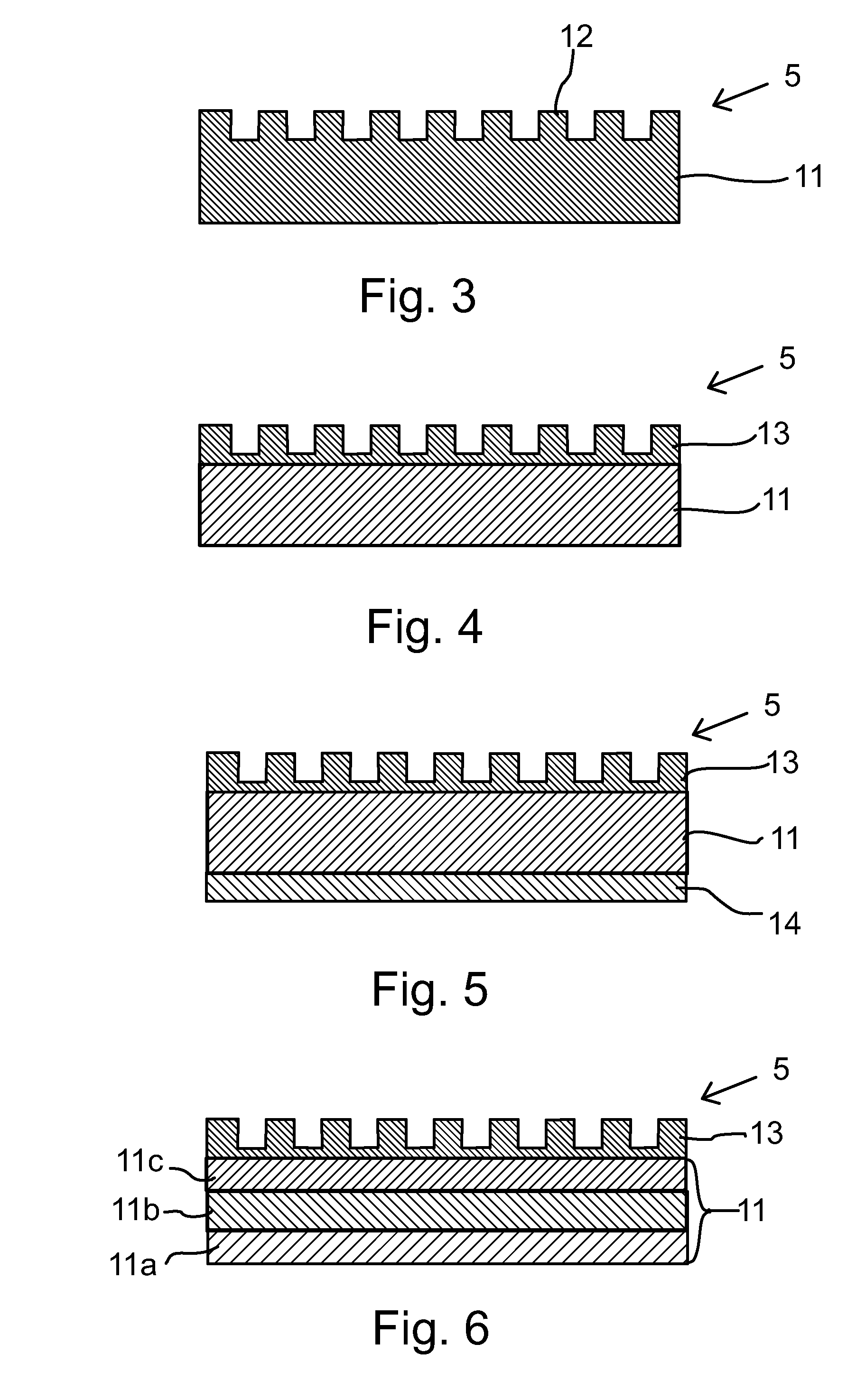
[0065]Master film: 50 micrometer thick polyester film with hot embossed diffractive grating, the distance of gratings from each other and the height of the gratings being 100 to 150 nanometers, coated with high refractive index based polymer coating.

Master film, 1000×200 mm, was taped on chill roll, diffractive grating towards the rubber pressure roller.

Results: diffractive gratings were copied equally well onto PE extruded on the carton board with all used line speeds, melting temperatures and nip pressures.


PUM

PropertyMeasurementUnit
temperatureaaaaaaaaaa
pressureaaaaaaaaaa
speedaaaaaaaaaa

Abstract

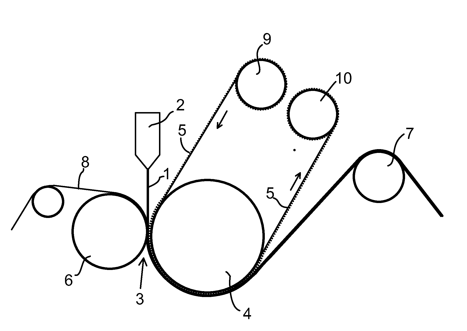
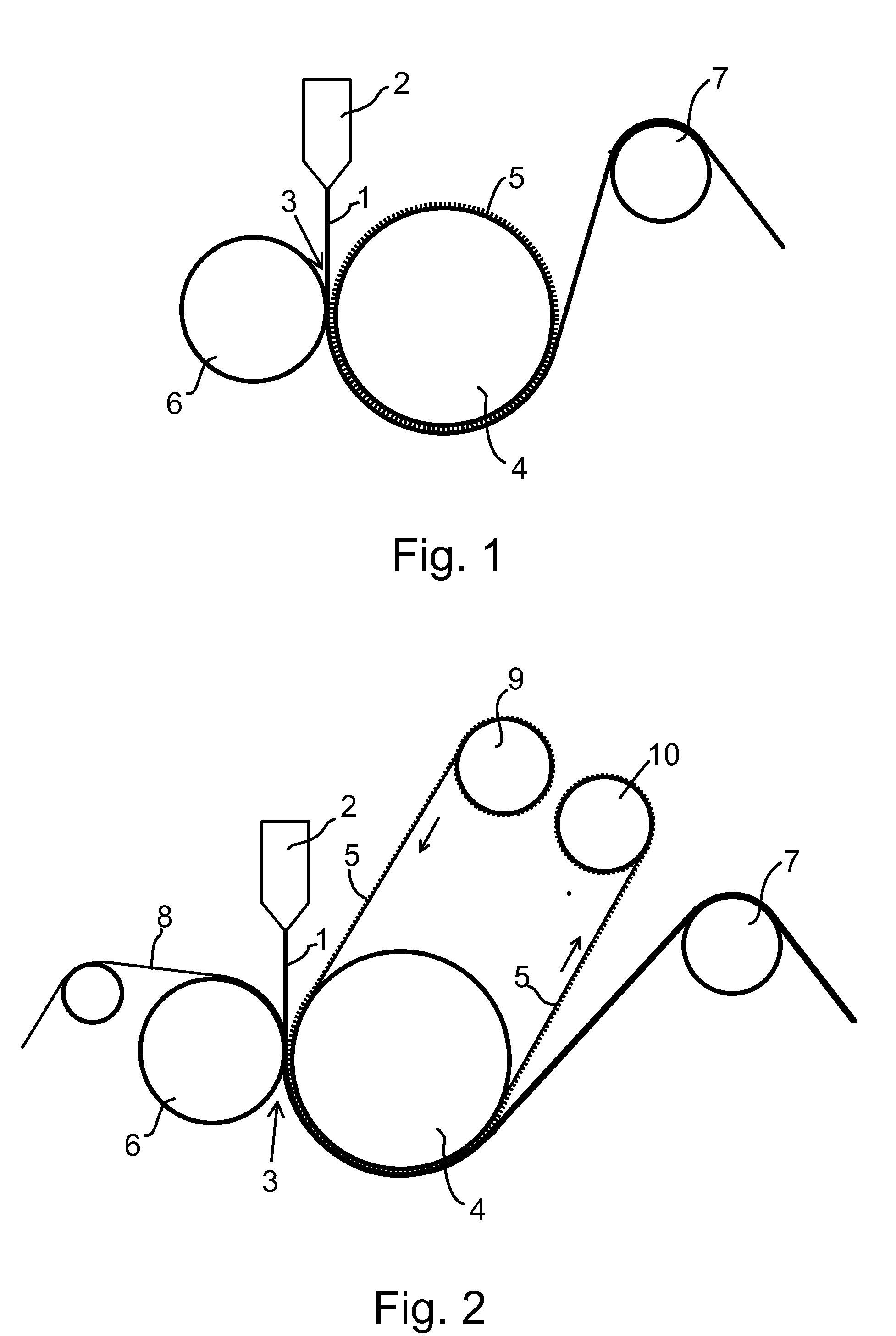
The invention relates to a method for producing micro- or nanostructures in polymer film materials having thermoforming properties in an extrusion process. The method according to invention comprises providing a molten thermoforming polymer film (1) from an extruder (2), driving a molten polymer film (1) through a nip (3) wherein the molten thermoforming polymer film (1) is contacted with a cooling roller (4) supporting a master film with a surface relief pattern (5) and a pressure roller (6), so that micro- or nanostructures are replicated onto the polymer film by the action of pressure and cooling at the nip. The master film is a polymeric master film it is driven continuously from the master film feed roller (9) through the nip (3) to the receiver roller (10).

Description

FIELD OF THE INVENTION[0001]The invention relates to a method for producing micro- or nanostructures in polymeric film materials having thermoforming properties, a master film with a surface relief pattern for producing micro- or nanostructures in polymer film materials having thermoforming properties and a use thereof.BACKGROUND OF THE INVENTION[0002]Two different basic techniques are used in continuous roll-to-roll manufacturing of macro- or nanostructures, for example diffractive optical elements, on flexible substrates. Hot embossing uses a metallic shim, typically a shim made of nickel, with which a fine structure is pressed into the surface of the heated polymer. Another method of producing diffractive optical elements is UV embossing, where a liquid monomer or polymer placed in a shim is hardened with the aid of ultraviolet light.[0003]Although industrial manufacturing of diffractive optical elements is comparatively simple, their manufacturing requires machines using high ni...

Claims


Application Information

Patent Timeline
Patent Type & Authority Applications(United States)
IPC IPC(8): B29C59/02B29C59/04B29C43/22
CPCB29C59/022B29C43/222B29L2011/00B29C2059/023B29K2101/12B29C59/04B29C59/046B29C43/28B29C43/24B29C59/16
Inventor HURME, EERORAUKOLA, JAAKKOKALIMA, VALTTERI
Owner ISCENT OY
Learn More