Communication system, management server, server, concentrator, and encryption setting method
- Summary
- Abstract
- Description
- Claims
- Application Information
AI Technical Summary
Benefits of technology
Problems solved by technology
Method used
Image
Examples
first embodiment
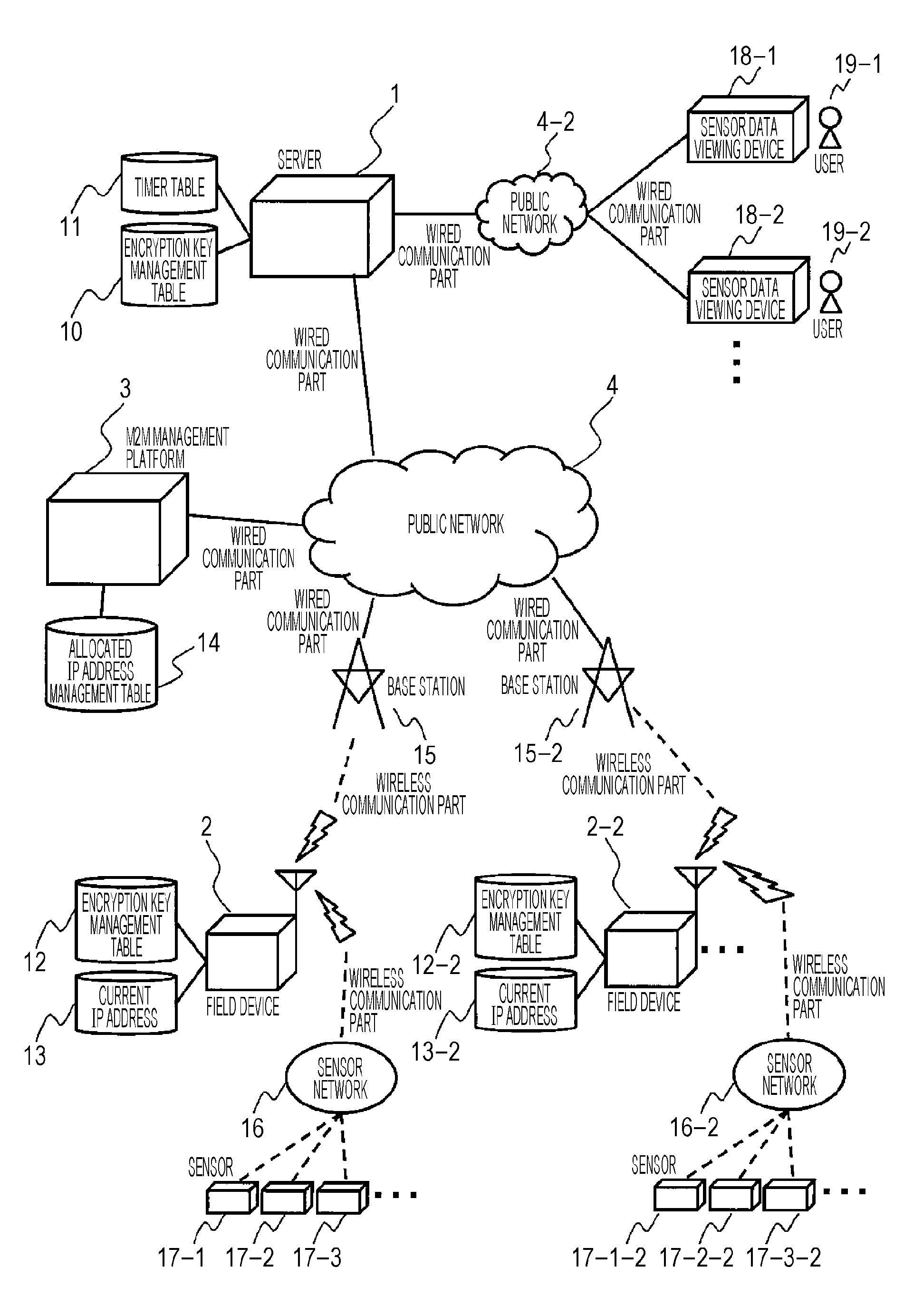
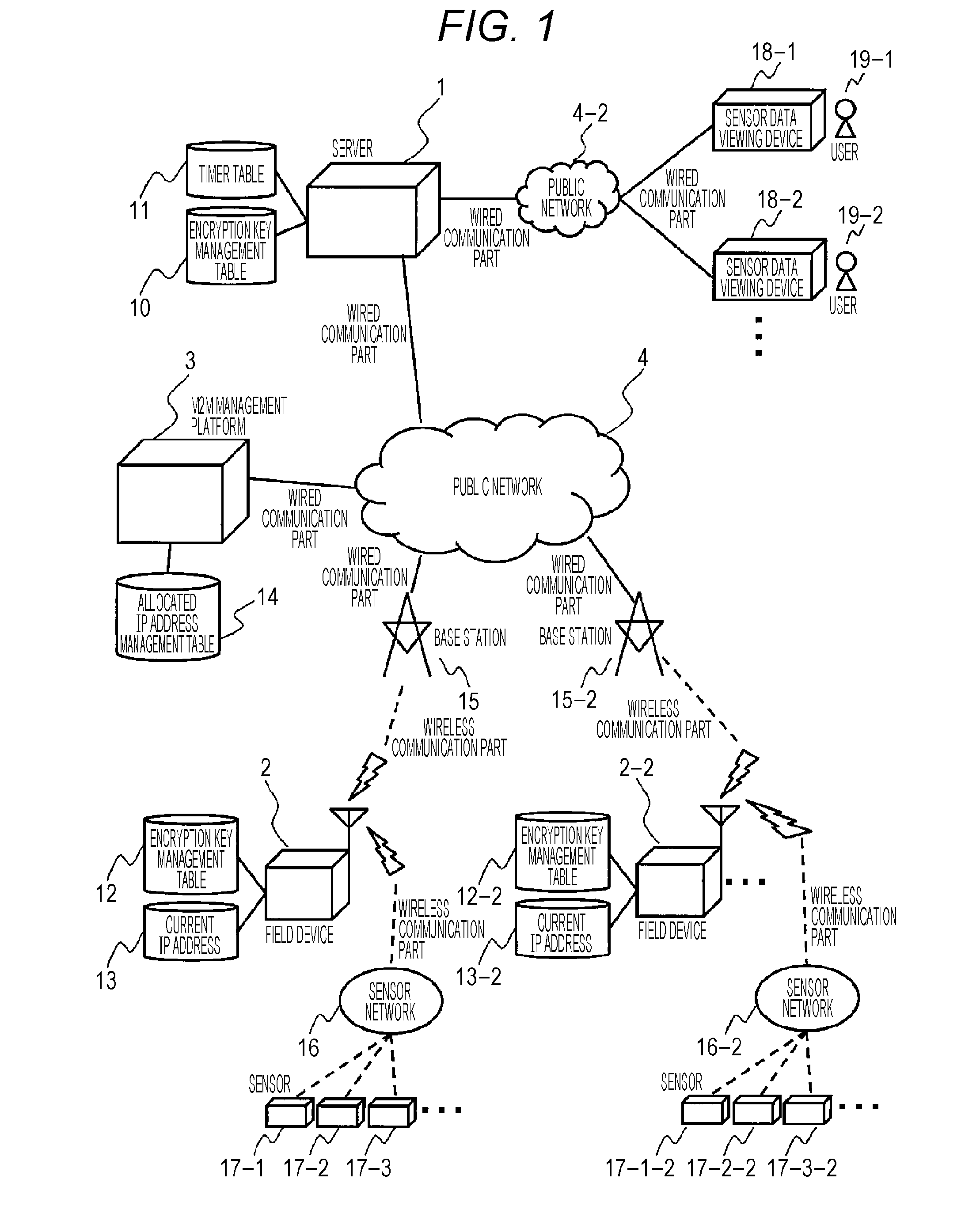
[0028]FIG. 1 is a configuration diagram of a network system according to the present embodiment.
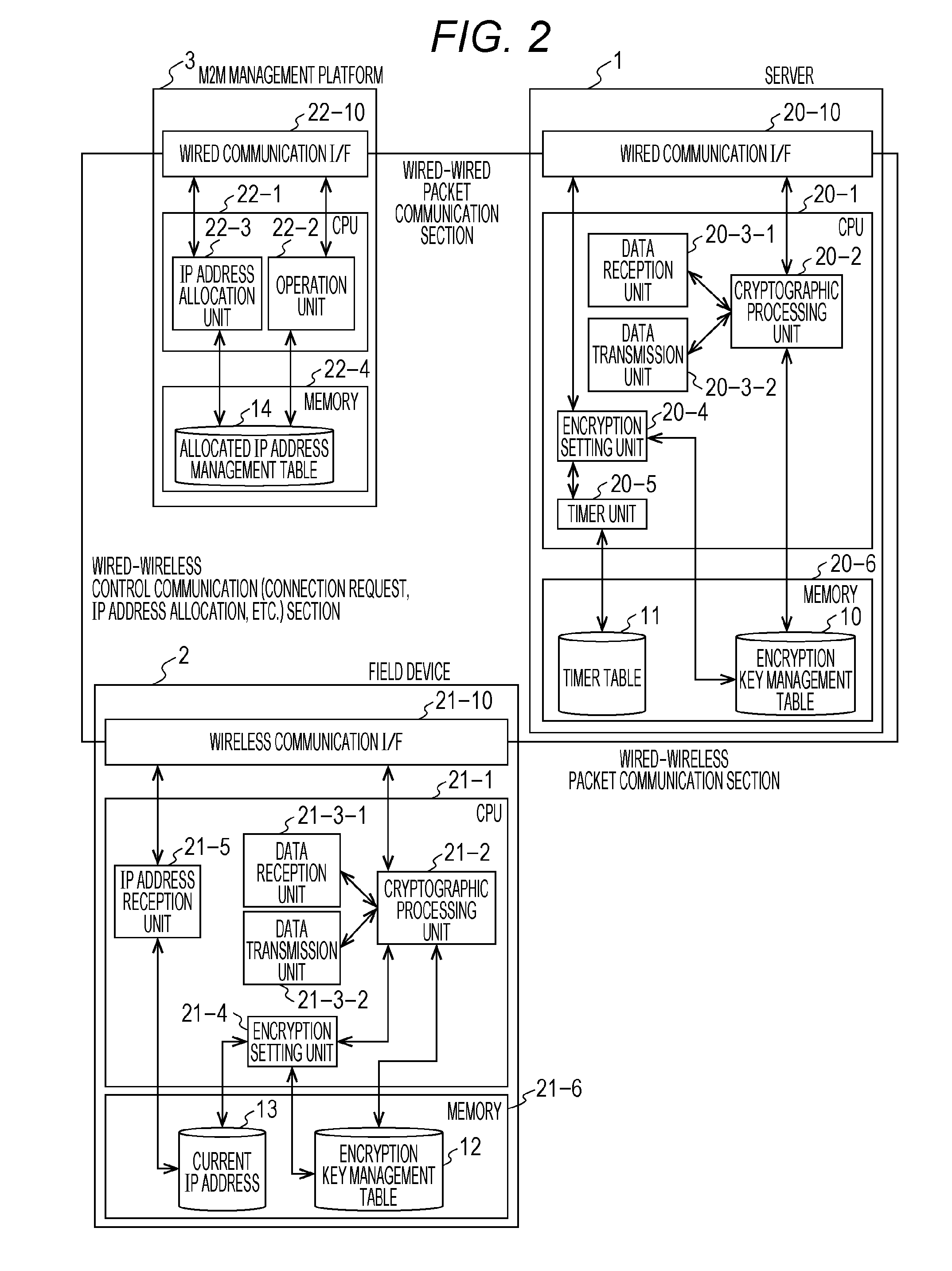
[0029]A server 1 is connected to a public network 4, and holds an encryption key management table 10 for transmission / reception of encrypted data from a field device 2 and a timer table 11 for management of transmission data periods. The server 1 transmits and receives packets to / from the field device 2 via the public network 4. The server 1 also conducts packet communication with an M2M management platform 3 via the public network 4.
[0030]The field device 2 is connected to the public network 4, and holds an encryption key management table 12 for transmission / reception of encrypted data to the server 1 and a current IP address 13. The field device 2 transmits and receives packets to / from the server 1 via the public network 4.
[0031]The field device 2 does not hold an IP address in advance. Instead, when the field device 2 connects to the public network 4, the field device 2 issues a connec...
second embodiment
[0126]The second embodiment is directed to reduce the number of inquiries in the processes of inquiring of the M2M management platform 3 an allocated IP address by the server 1 in step 70-2 when the number of field devices 2 in a network system is larger.
[0127]FIG. 10 illustrates details of the timer table 11 of the server 1 according to the second embodiment.
[0128]The timer table 11 of the second embodiment further holds a time range 100-1.
[0129]While different next IP address check time 50-4 is specified for different field device ID 50-1 in the timer table 11 of the first embodiment, the time range 100-1 of IP address check is specified and the next IP address check times 50-4 of one or more field devices whose next communication times 50-3 fall within the range are set to the same timing in the timer table 11 of the second embodiment.
[0130]As a result, the operations in the steps of the encryption setting unit 20-4 of the server 1 in the first embodiment as illustrated in FIG. 7...
third embodiment
[0137]The third embodiment is directed to prevent a packet loss when the IP address of a field device 2 is changed and when both a packet encrypted before the IP address change and a data packet encrypted after the IP address change may be present.
[0138]In the first embodiment, when the server 1 checks the IP address change of a field device 2 in step 70-2 of FIG. 7, a row of the encryption key management table 10 in FIG. 3A is also changed in step 70-3. Thus, if a data packet encrypted before the IP address change is present, the data packet encrypted before the IP address change cannot be received if the encryption key management table 10 of FIG. 3B is used.
[0139]FIG. 11 illustrates details of the encryption key management table 10 of the server 1 according to the third embodiment.
[0140]When the server 1 has detected an IP address change of a field device 2 in step 70-2, while the field device IP address 30-2 is changed as illustrated in FIG. 3B in the encryption key management ta...
PUM
 Abstract
Description
Claims
Application Information
 - R&D
- Intellectual Property
- Life Sciences
- Materials
- Tech Scout
- Unparalleled Data Quality
- Higher Quality Content
- 60% Fewer Hallucinations
Browse by: Latest US Patents, China's latest patents, Technical Efficacy Thesaurus, Application Domain, Technology Topic, Popular Technical Reports.
© 2025 PatSnap. All rights reserved.Legal|Privacy policy|Modern Slavery Act Transparency Statement|Sitemap|About US| Contact US: help@patsnap.com


