
Welded roof for modular building units

a modular building and welded technology, applied in the direction of building roofs, roof drainage, building repairs, etc., can solve the problems of water leakage around the screws and into the building unit, and achieve the effect of easy vertical stacking of modular building units on top of one, and easy carrying heavy loads

Active Publication Date: 2016-01-21
WILLIAMS SCOTSMAN INC
View PDF0 Cites 15 Cited by
  • Summary
  • Abstract
  • Description
  • Claims
  • Application Information

AI Technical Summary

Benefits of technology

The patent is about a roof assembly for modular building units. The roof is made by welding a sheet of roofing material onto the frame of the building unit, creating a continuous, sealed weld that prevents water from entering. The roof is pitched to direct water away from the building, but can still handle heavy snow loads. The welded roof avoids the need for screws and specialized holes, and can have a single slope through the roof. The roof also allows for easy stacking of the building units on top of each other. Overall, the welded roof is watertight, strong, and easy to install.

Problems solved by technology

The welded roofing sheet avoids the use of screws, and the associated possibility of water leakage around the screws and into the building unit.

Method used


Image

  • Welded roof for modular building units
  • Welded roof for modular building units
  • Welded roof for modular building units

Examples


Embodiment Construction

[0031]The following description is of a particular embodiment of the invention, set out to enable one to practice an implementation of the invention, and is not intended to limit the preferred embodiment, but to serve as a particular example thereof. Those skilled in the art should appreciate that they may readily use the conception and specific embodiments disclosed as a basis for modifying or designing other methods and systems for carrying out the same purposes of the present invention. Those skilled in the art should also realize that such equivalent assemblies do not depart from the spirit and scope of the invention in its broadest form.

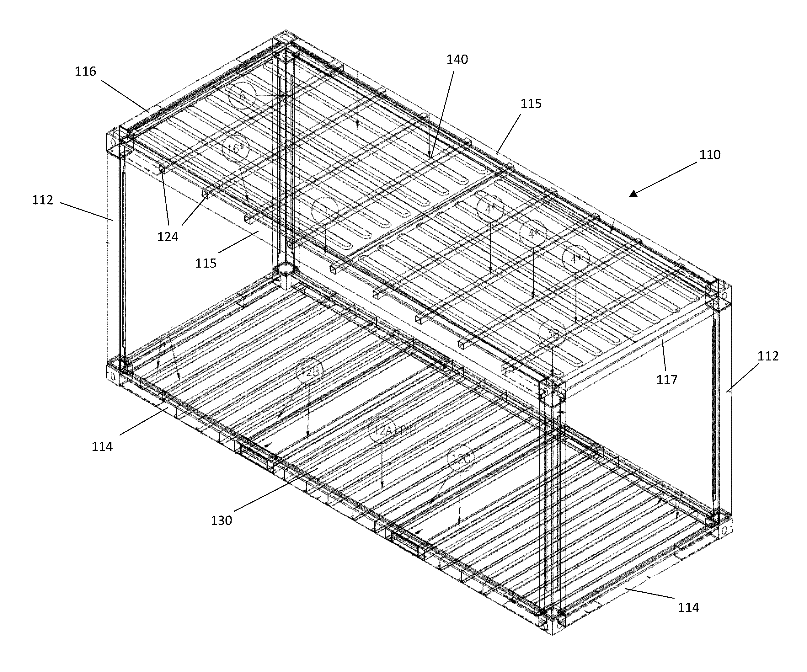
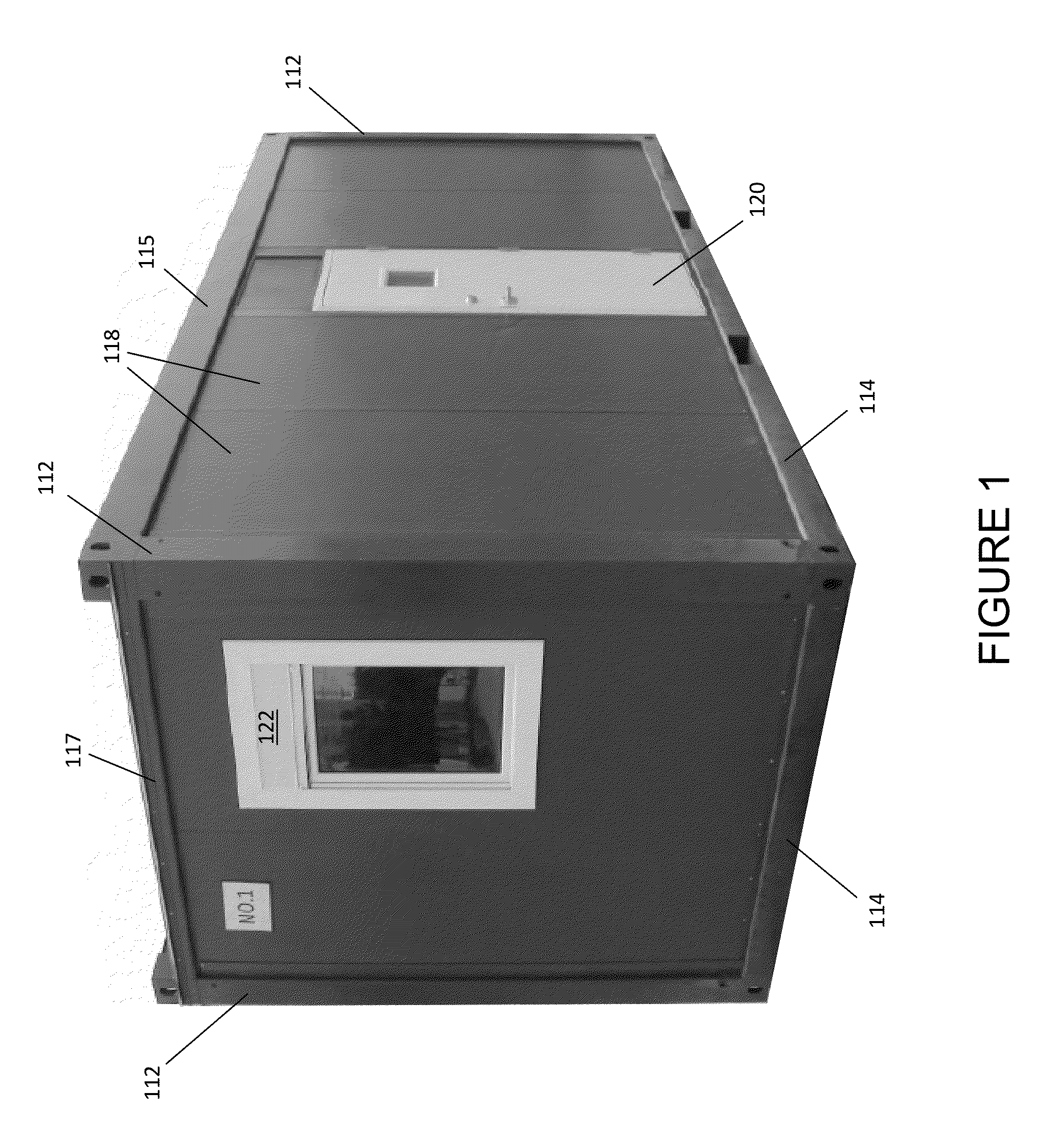
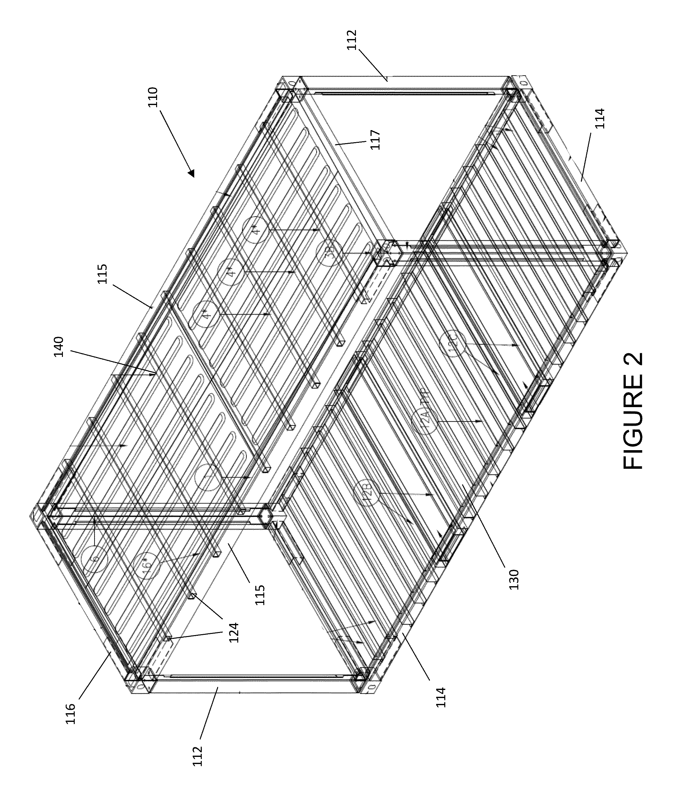
[0032]FIG. 1 provides a perspective view of a modular building unit 100 in accordance with certain aspects of an embodiment of the invention. Modular building unit 100 includes a skeletal frame formed by corner support posts 112, bottom rails 114, top long rails 115, a first top short rail 116 (shown in FIG. 2), and a second top short rail 117. ...


PUM


Abstract

Disclosed is a roof assembly for a modular building unit that comprises a roofing sheet that is welded to the frame of the modular building unit to form a unitary, continuous sealed weld between the roofing sheet and the generally horizontal structural frame of the modular building unit, and that is pitched to downwardly direct water toward one end of the modular building unit. The welded roof assembly prevents water infiltration into the modular building unit, and such watertight structure may then receive any gutter configuration the user wishes to implement without risking water infiltration into the building unit. The welded roofing sheet avoids the use of screws or other fasteners, and the associated possibility of water leakage around the screws and into the building unit. The welded roof also is able to employ a single slope all of the way through the full span of the roof, thus avoiding the need for a centrally pitched roof assembly, and its unitary construction avoids the tiling effect that results from the use of multiple, overlapping roofing sheets. The welded roof also avoids the need for silicon or other filler agents between the unitary roofing sheet and the frame of the modular building unit.

Description

CROSS REFERENCE TO RELATED APPLICATION[0001]This application is based upon and claims benefit of copending U.S. Provisional Patent Application Ser. No. 62 / 026,249 entitled “WELDED ROOF FOR MODULAR BUILDING UNITS,” filed with the U.S. Patent and Trademark Office on Jul. 18, 2014 by the inventor herein, the specification of which is incorporated herein by reference in its entirety.FIELD OF THE INVENTION[0002]This invention relates generally to modular building construction, and more particularly to a welded roof assembly for a modular building unit configured to receive various gutter system configurations.BACKGROUND OF THE INVENTION[0003]Roofing members for modular buildings are typically attached by way of screws or other fasteners, and are supplied in sheets arranged in a tile configuration with a portion of one roofing sheet overlapping a portion of an adjacent roofing sheet. In order to channel rainwater and water from snow and ice melt away from the modular building, gutters may...

Claims


Application Information

Patent Timeline
Patent Type & Authority Applications(United States)
IPC IPC(8): E04D13/04E04B7/18E04D3/40E04D13/064E04H1/00E04H1/12
CPCE04D13/04E04H1/005E04H1/12E04H2001/1283E04D3/40E04D13/064E04B7/18E04B1/3483
Inventor BOTTIN, HERVE
Owner WILLIAMS SCOTSMAN INC
Learn More