
Capture block assembly for retaining shackles

a technology of retaining shackles and capture blocks, which is applied in the direction of transportation and packaging, manufacturing tools, hoisting equipment, etc., can solve the problems of affecting the safety of personnel or property, and the component of said wire rope slings can sometimes fail or suffer damage, so as to prevent unwanted swapping, interchanging or replacing the capture block

Active Publication Date: 2016-01-07
FOLEY PATENTS
View PDF11 Cites 6 Cited by
  • Summary
  • Abstract
  • Description
  • Claims
  • Application Information

AI Technical Summary

Benefits of technology

The present invention is a capture block assembly for use in rigging hardware such as wire rope sling assemblies. It prevents the removal of a shackle from a wire rope sling assembly, which helps prevent unwanted swapping, interchanging, or replacement of shackles. This invention also provides a single safety certification for an entire lifting assembly, rather than requiring individual certification of each component. The capture block assembly can be permanently installed, such that it cannot be easily removed from the assembly without causing damage. It includes at least one cylindrical pin or other fastener that acts as a rivet binding the capture block members together, permanently fixing the capture block assembly within the thimble.

Problems solved by technology

In several of these applications, safety is a paramount concern, as such rigging equipment can be used for heavy overhead lifting; dropping or imprecise placement of such heavy loads can cause injury or death to personnel or property.
Said wire rope sling assemblies are often used in heavy duty lifting operations and, thus, can be placed under great loading stress and tension when in use.
As a result, a component of said wire rope slings can sometimes fail or suffer damage during use, and users may replace individual components with spare parts from other sling assemblies.
In many cases, said sling assemblies can be outfitted with cheaper or lower quality components, thereby compromising the overall integrity and lifting capacity of the wire rope sling assembly.
In addition to being unsafe, this practice can subject a manufacturer and / or user of such a wire rope sling assembly to liability in the event of a failure.
If at least one shackle is changed or replaced without authorization, then a traceable record is no longer complete and accurate.
Moreover, it is not advisable or safe to perform welding on a thimble member after assembly of a wire rope sling assembly because the heat from the welding operations will be transferred through the thimble and into the wire rope, thereby changing the strength properties of said wire rope.

Method used


Image

  • Capture block assembly for retaining shackles
  • Capture block assembly for retaining shackles
  • Capture block assembly for retaining shackles

Examples


Embodiment Construction

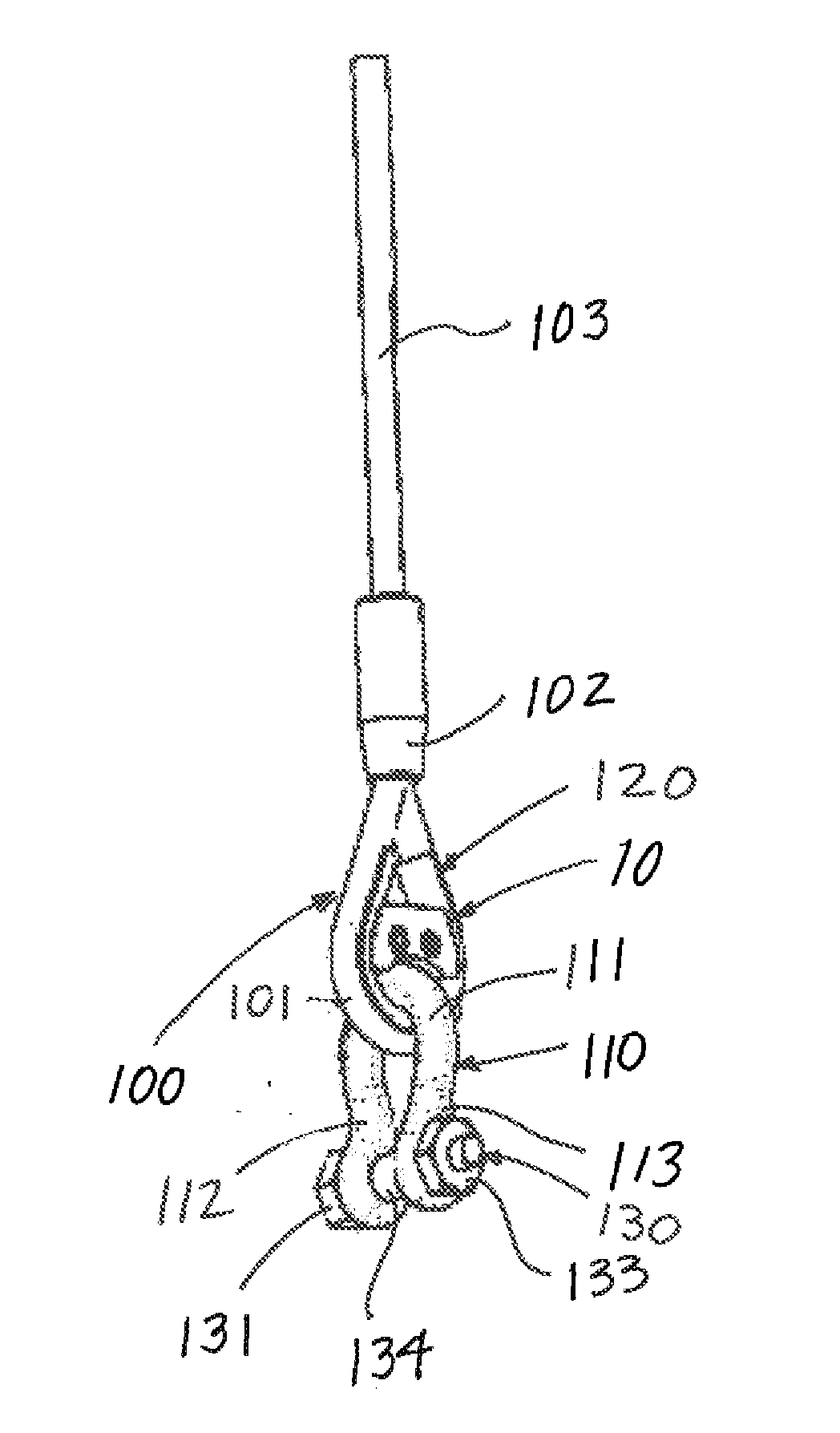
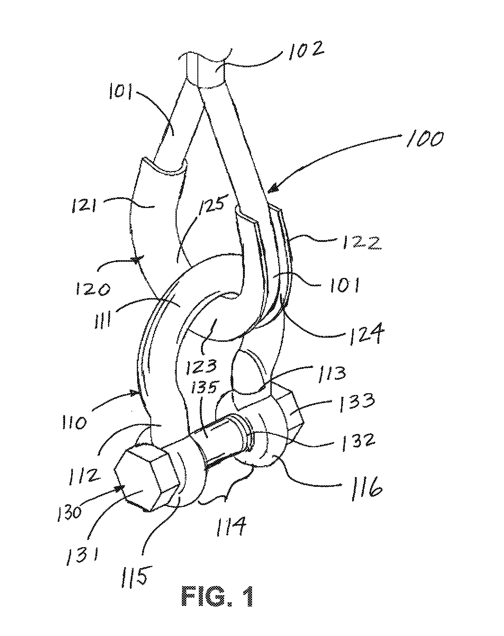
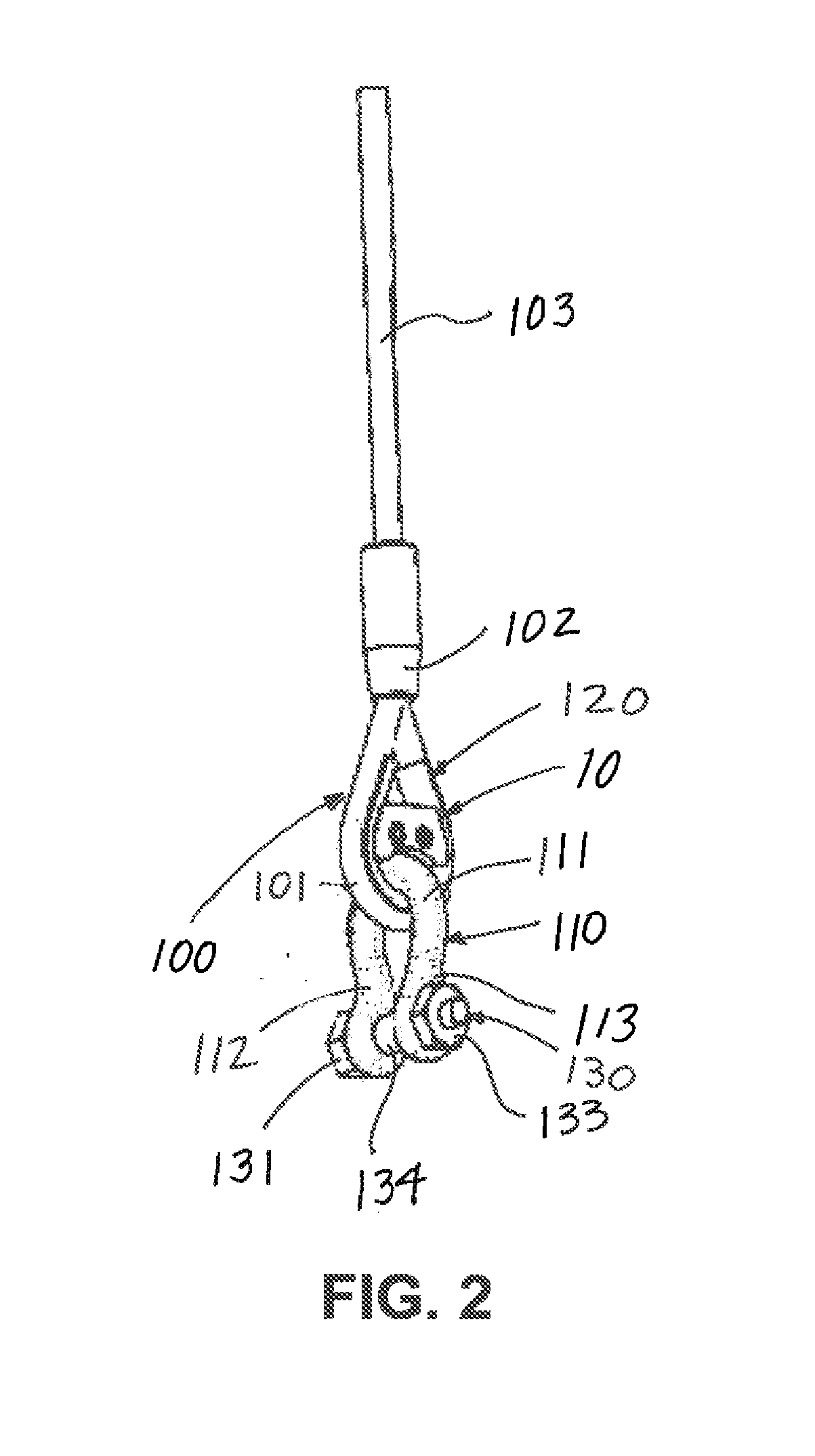
[0031]Referring to the drawings, FIG. 1 depicts a side perspective view of a portion of a conventional wire rope sling assembly 100. The portion of wire rope sling 100 depicted in FIG. 1 generally comprises a length of wire rope formed into loop section 101 and securely joined together at connection junction 102. A conventional fitting such as, for example, a clamp, clip, socket, or swaged fitting can be used to secure a loose end of said wire rope back to said main wire rope body at connection junction 102.

[0032]Substantially rigid thimble member 120 is installed within said loop section 101. Conventional thimble member 120 generally comprises first leg member 121, second leg member 122 and curved central arch member 123. A peripheral groove 124 extends substantially along the outer surface of said thimble member 120 for receiving wire rope loop 101 within said peripheral groove 124. Thimble member 120 further comprises curved inner surface 125 having a substantially convex outer s...


PUM


Abstract

A capture block assembly prevents unauthorized removal, swapping, interchanging or replacement of shackle members used with conventional wire rope sling assemblies. A first half member is permanently joined with a second half member within a thimble member of a sling loop, after a wire rope sling has been manufactured or assembled, to prevent removal of a shackle from such loop. No welding or other operations permanently affecting strength properties of the thimble or sling member is required.

Description

CROSS REFERENCES TO RELATED APPLICATION[0001]Priority OF U.S. Provisional Patent Application Ser. No. 62 / 020,610, filed Jul. 3, 2014, incorporated herein by reference, is hereby claimed.STATEMENTS AS TO THE RIGHTS TO THE INVENTION MADE UNDER FEDERALLY SPONSORED RESEARCH AND DEVELOPMENT[0002]NONEBACKGROUND OF INVENTION[0003]1. Field of the Invention[0004]The present invention pertains to a capture block assembly for use in preventing a shackle attached to a wire rope lifting assembly from being removed from said wire rope assembly without removal or destruction of said capture block assembly.[0005]2. Brief Description of the Prior Art[0006]Riggings of various types are commonly used in industrial applications, including, but not limited to, oil and gas well drilling, mining operations, the nuclear energy industry, and many others. In several of these applications, safety is a paramount concern, as such rigging equipment can be used for heavy overhead lifting; dropping or imprecise pl...

Claims


Application Information

Patent Timeline
IPC IPC(8): B66C1/66
CPCB66C1/66F16G11/00B66C1/12F16G11/146F16G15/06
Inventor FOLEY, LAWRENCE E.FOLEY, SCOTT C.
Owner FOLEY PATENTS
Learn More