
Mesoporous Structure Solar Cell with Siloxane Barrier

a solar cell and membrane technology, applied in the field of solar cells, can solve the problems of remaining perovskite decomposition at the tiosub>2/sub>/perovskite interface, polycrystallinity and potential problems with grain boundaries, etc., and achieve the effect of effective passivation, good passivation, and facilitate the proper formation of the perovskite layer

Inactive Publication Date: 2015-12-31
SHARP LAB OF AMERICA INC
View PDF2 Cites 7 Cited by
  • Summary
  • Abstract
  • Description
  • Claims
  • Application Information

AI Technical Summary

Benefits of technology

This patent describes a solar cell that uses a special design to improve the performance of perovskite cells. The design uses passivating molecules that anchor the perovskite to the surface of the cell and prevent it from decomposing when exposed to light. The passivating molecules have two active ends - one that attaches to the perovskite structure and the other that attaches to the metal oxide surface. These molecules have a specific structure that controls the transfer of ions and electrons between the perovskite and metal oxide, resulting in more efficient solar cell performance.

Problems solved by technology

Despite the remarkable photovoltaic performances that have been demonstrated for the perovskite cells, a PCE as high as 15%, a number of issues remained.
One of the challenges is related to the overall devices stability, especially the decomposition of the perovskite material in the presence of moisture and light, or the combination these effects.
In addition, the crystallization of the perovskite material on the TiO2 surface is random, thus leading to polycrystallinity and potential problems with grain boundaries.
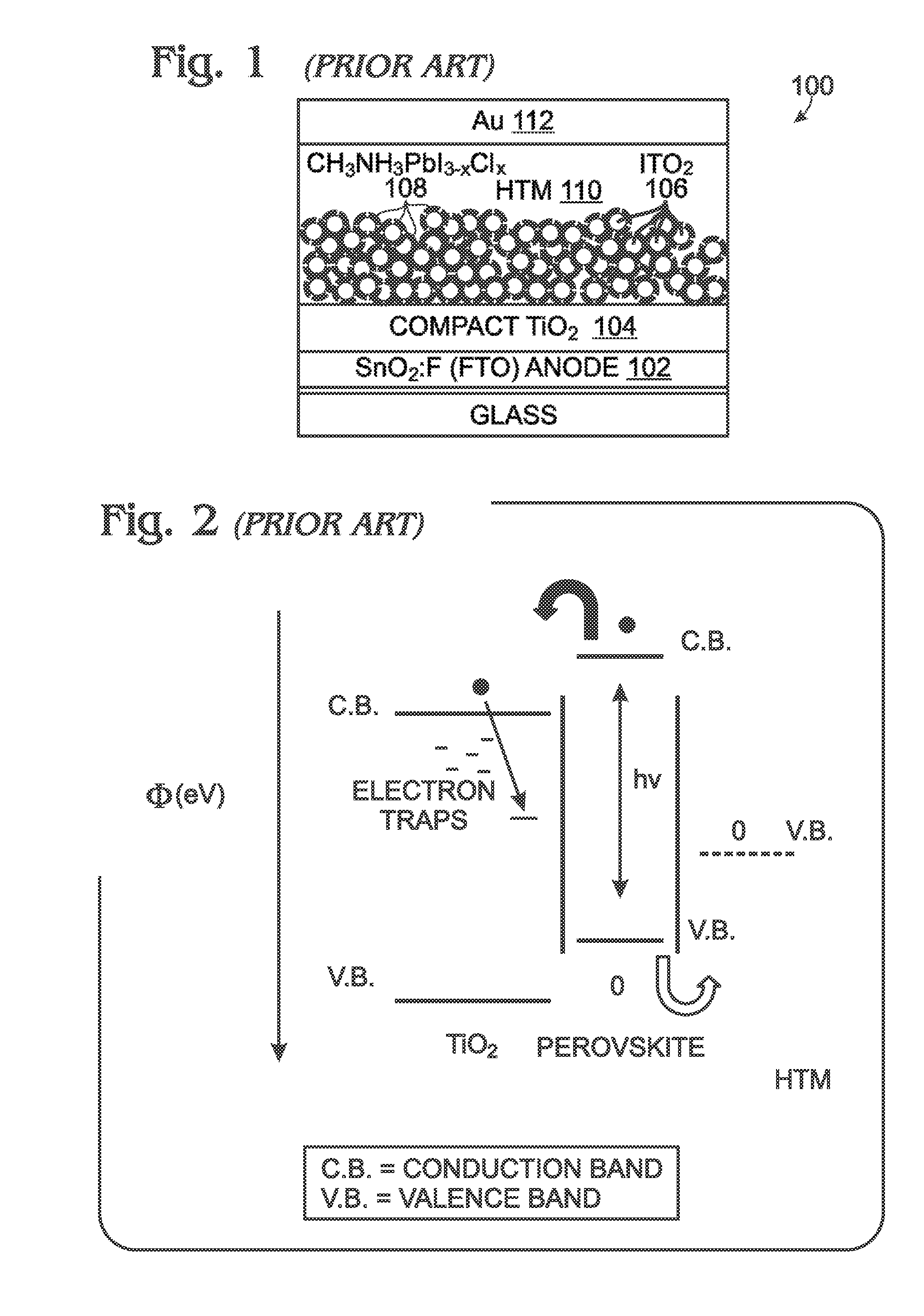
However, the problem of perovskite decomposition at the TiO2 / perovskite interface remains (Nature Comm., 2013, 4, 2885).
In this case, the transport of the negative charges occurs through the network of the perovskite material, as injection of electron into Al2O3 is energetically unfavorable.

Method used


Image

  • Mesoporous Structure Solar Cell with Siloxane Barrier
  • Mesoporous Structure Solar Cell with Siloxane Barrier
  • Mesoporous Structure Solar Cell with Siloxane Barrier

Examples


Embodiment Construction

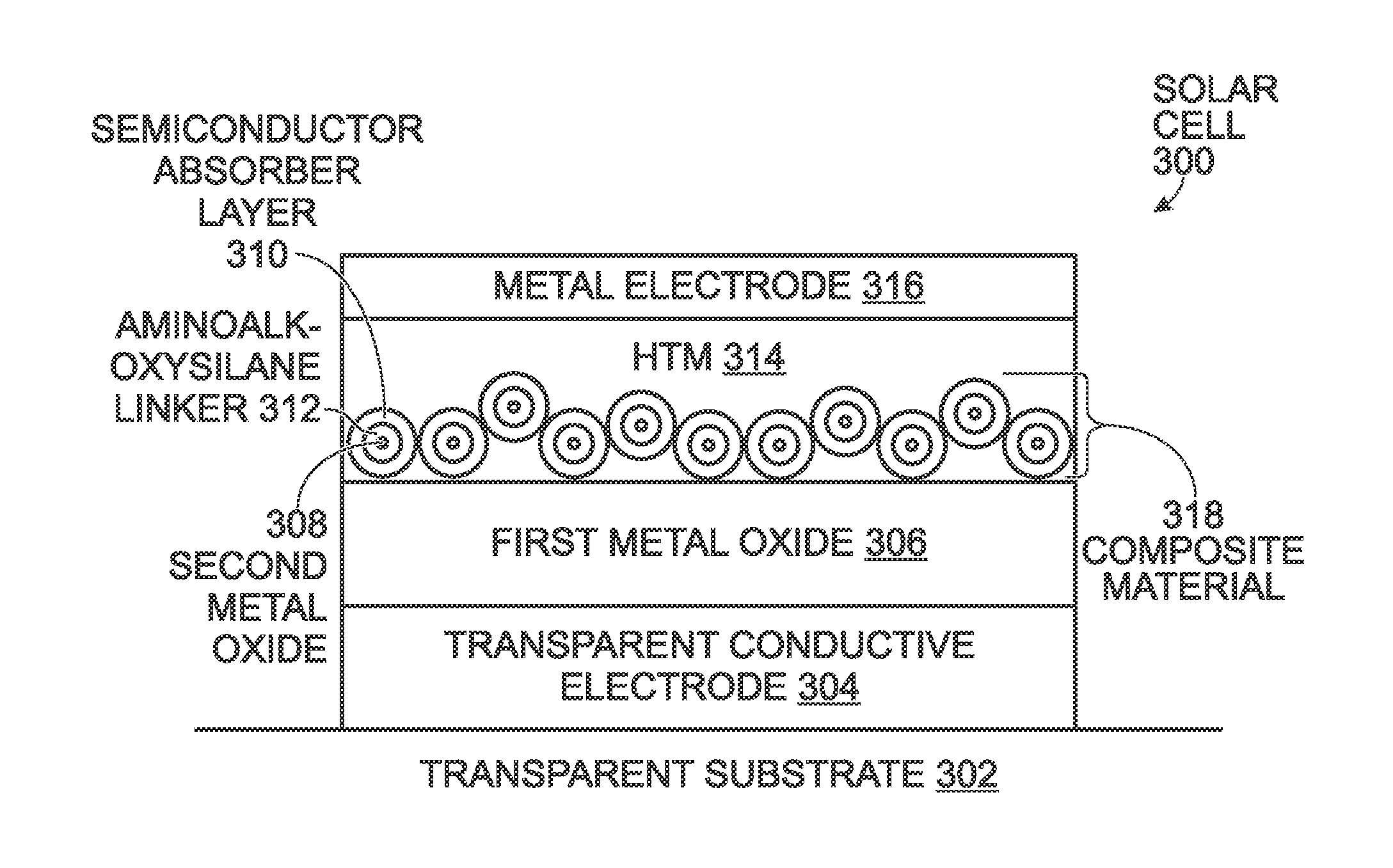
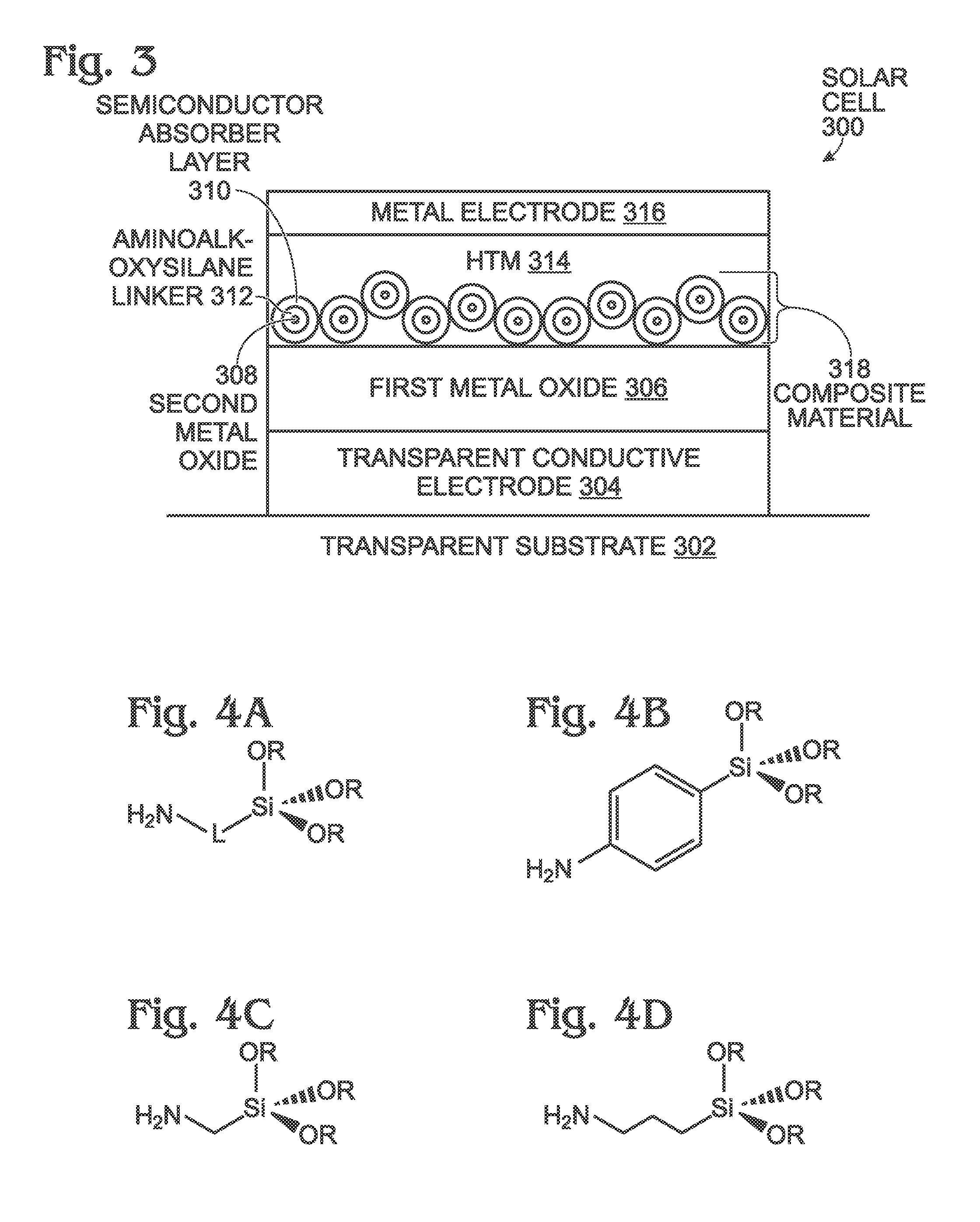
[0031]FIG. 3 is a partial cross-sectional view depicting a mesoporous-structured solar cell with a silane or siloxane barrier. The solar cell 300 comprises a transparent substrate 302. Silica (glass), quartz, or a plastic may be used as the transparent substrate 302. A transparent conductive electrode 304 overlies the transparent substrate 302. Fluorine-doped tin oxide (SnO2:F) can be used as the transparent conductive electrode 304. Forms of graphene, indium tin oxide (ITO), indium gallium zinc oxide (IGZO), other conductive metal oxides, and single-walled carbon nanotubes may also possibly be used as a transparent conductive electrode material. A non-mesoporous layer of a first metal oxide 306 overlies the transparent conductive electrode 304. A mesoporous layer of a second metal oxide 308 overlies the non-mesoporous layer of first metal oxide 306. A mesoporous material is a material containing pores with diameters between 2 and 100 nanometers (nm).

[0032]Generally, the first metal...


PUM

PropertyMeasurementUnit
diametersaaaaaaaaaa
diametersaaaaaaaaaa
transparentaaaaaaaaaa

Abstract

A method is provided for forming a mesoporous-structured solar cell with a silane or siloxane barrier. The method forms a transparent conductive electrode overlying a transparent substrate. A non-mesoporous layer of a first metal oxide overlies the transparent conductive electrode, with a mesoporous layer of a second metal oxide overlying the non-mesoporous layer of first metal oxide. An aminoalkoxysilane layer overlies the mesoporous layer of second metal oxide. Over the aminoalkoxysilane layer is deposited a semiconductor absorber layer comprising organic and inorganic components. Using the aminoalkoxysilane linker, the mesoporous layer of second metal oxide is linked to the semiconductor absorber layer. A hole-transport material (HTM) layer is formed overlying the semiconductor absorber layer, and a metal electrode overlies the HTM layer. A mesoporous-structured solar cell with a silane or siloxane barrier is also provided.

Description

RELATED APPLICATIONS[0001]This application is a Continuation-in-part of a patent application entitled, SURFACE-PASSIVATED MESOPOROUS STRUCTURE SOLAR CELL, invented by Changqing Zhan et al., U.S. Ser. No. 14 / 320,488, filed Jun. 30, 2014, attorney docket No. SLA3383, which is incorporated herein by reference.BACKGROUND OF THE INVENTION[0002]1. Field of the Invention[0003]This invention generally relates to solar cells and, more particularly, to a mesoporous-structure solar cell using a siloxane barrier.[0004]2. Description of the Related Art[0005]As evolved from dye-sensitized solar cells (DSSCs or DSCs), perovskite-sensitized solar-cells have recently attracted a great deal attention with a record high efficiency breakthrough (>17%) based upon low cost organometal trihalide perovskite absorbers. It has been suggested that with optimization of the cell structure, light absorber, and hole conducting material, this technology could advance to an efficiency that surpasses that of copp...

Claims


Application Information

Patent Timeline
Patent Type & Authority Applications(United States)
IPC IPC(8): H01G9/20H01L51/00H10K99/00
CPCH01G9/2036H01L51/4226Y02E10/549H10K30/151H10K85/50H10K30/50
Inventor KOPOSOV, ALEXEYZHAN, CHANGQINGPAN, WEI
Owner SHARP LAB OF AMERICA INC
Learn More