Control device for vehicle

Inactive Publication Date: 2015-12-24
TOYOTA JIDOSHA KK
View PDF6 Cites 4 Cited by
  • Summary
  • Abstract
  • Description
  • Claims
  • Application Information

AI Technical Summary

Benefits of technology

The invention provides a control device for vehicles that reduces shocks during running. This is achieved by using a motor and transmission configuration with an inverter that is set to a sinusoidal wave mode for vibration damping control. This improves the responsiveness of the motor torque, resulting in better road quality and reduced vehicle shock. Additionally, when the engine is starting up, the inverter mode is set to the sinusoidal wave mode to improve the accuracy of vibration damping control and increase fuel efficiency.

Problems solved by technology

However, the conventional arts only describe that consideration is given to the efficiency of the motor, and no consideration is given to the control mode of the inverter when the vibration damping control is performed in the conventional arts.
As a result, in a case where the vibration damping control is required such as the time of the engine start or the like, the control mode of the inverter having low responsiveness of the motor torque is sometimes selected so that there has been a possibility that a vehicle shock then occurs and drivability is deteriorated.

Method used


Image

  • Control device for vehicle
  • Control device for vehicle
  • Control device for vehicle

Examples


Embodiment Construction

[0024]Hereinbelow, embodiments of the invention will be described in detail with reference to the drawings. Note that figures are simplified or deformed as needed in the following embodiments, and dimensions and shapes of individual portions are not necessarily precisely depicted.

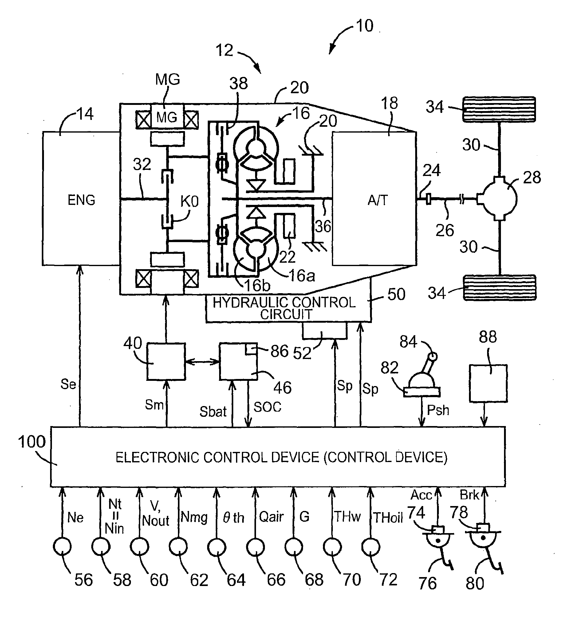
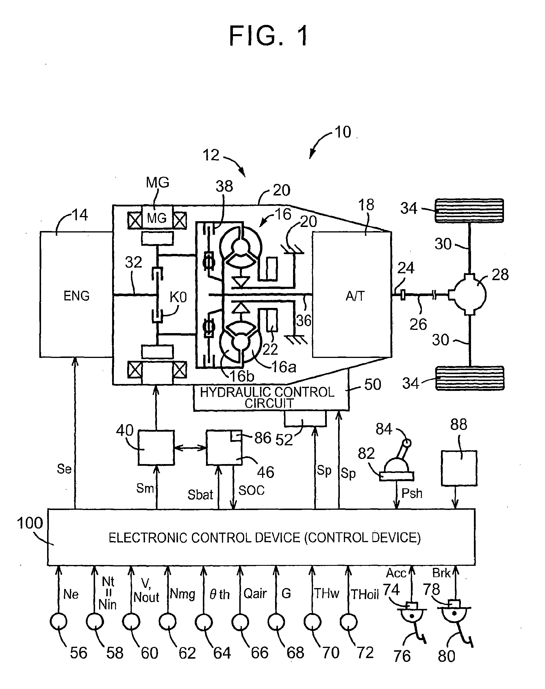
[0025]FIG. 1 is a view for explaining the schematic configuration of a power transmission path from an engine 14 and a motor MG that constitute a hybrid vehicle 10 (hereinafter referred to as a vehicle 10) to which the invention is preferably applied to driving wheels 34, and is also a view for explaining the principal portion of a control system provided in the vehicle 10 in order to perform an output control of the engine 14 functioning as a driving force source for running, a gear shifting control of an automatic transmission 18, and a drive control of the motor MG.

[0026]In FIG. 1, a vehicle power transmission device 12 (hereinafter referred to as a power transmission device 12) includes an engine diseng...


PUM


Abstract

A control device for a vehicle including: a motor; a transmission provided in a path that transmits drive power between the motor and a driving wheel; an inverter configured to drive the motor; a controller configured to control the inverter by using a plurality of control modes including a sinusoidal wave mode to thereby drive the motor, the controller configured to select the control mode in accordance with a gear position of the transmission, the controller configured to select the gear position by which the sinusoidal wave mode is selected when the motor controlled by the controller suppresses a vibration of the vehicle.

Description

BACKGROUND OF THE INVENTION[0001]1. Field of the Invention[0002]The invention relates to a technology for improving controllability of a motor functioning as a driving force source in a vehicle configured to include the motor.[0003]2. Description of Related Art[0004]There is available a vehicle that includes a motor and a transmission provided in a power transmission path between the motor and driving wheels. Examples of the vehicle include vehicles described in Japanese Patent Application Publication No. 2000-236601 (JP 2000-236601 A) and Japanese Patent Application Publication No. 2004-28280 (JP 2004-28280 A). The vehicle in JP 2000-236601 A is configured to include an engine 2, a motor 4, a clutch 3 provided in a power transmission path between the engine 2 and the motor 4, and a continuously variable transmission 5 provided in the power transmission path between the motor 4 and driving wheels 8. The vehicle in JP 2004-28280 A is configured to include an engine 2, a motor generat...

Claims


Application Information

Patent Timeline
IPC IPC(8): B60L15/06B60L50/16
CPCB60L15/06B60W10/06B60W10/08B60W10/115B60W20/40B60W30/1882B60W2030/206B60W2510/1005B60W2710/083B60W2710/1005Y02T10/62Y02T10/7072Y02T10/72B60L15/025B60L15/08B60L2240/14B60L2240/421B60L2240/423B60L2240/441B60L2240/443B60L2240/486B60L2240/507B60L2270/145B60L50/16Y02T10/64Y02T10/70
Inventor YAGUCHI, HIDEAKI
Owner TOYOTA JIDOSHA KK
Why Eureka
Try Eureka