
Synchronous Rectifier Design for Wireless Power Receiver

a synchronous rectifier and wireless power technology, applied in the field of wireless power transmission, can solve the problems of increasing the amount of power required and consumed by battery-powered electronic devices, inherently inefficient conductors, and inefficiency of diodes, so as to reduce forward voltage drop and improve power transfer efficiency, the effect of less loss switching

Inactive Publication Date: 2015-11-12
ENERGOUS CORPORATION
View PDF14 Cites 202 Cited by
  • Summary
  • Abstract
  • Description
  • Claims
  • Application Information

AI Technical Summary

Benefits of technology

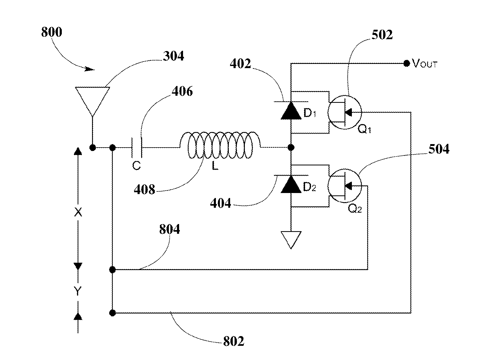
The patent text describes different circuit topologies for synchronous rectifier circuits that are designed to be low-cost, low-complexity, and small in size. The circuits are capable of operating at high switching frequencies, reducing reverse recovery losses and voltage stresses, thus minimizing power loss. One circuit topology uses a delay-locked loop (DLL) clock to control the switching of FET transistors, allowing for practically lossless switching and reduced forward voltage drop, improving efficiency of power transfer. Another circuit topology uses phase shifters to drive FET transistors, providing significantly less loss switching and reduced forward voltage drop, improving efficiency of power transfer. Additionally, a synchronous rectifier circuit topology is described that uses wavelength links for switching control, which provides the required phase shifting to enable proper timing for current to flow through diodes coupled to FET transistors and ensures high conduction times, resulting in significantly less loss switching and reduced forward voltage drop, and improving efficiency of power transfer.

Problems solved by technology

While battery technology has improved, battery-powered electronic devices increasingly require and consume greater amounts of power, thereby often requiring recharging.
A typical half-bridge rectifier include two diodes which are inherently inefficient conductors producing a number of well-known problems.
One problem resulting from the inefficiency of diodes is that they produce a forward voltage drop.
Schottky diodes, which exhibit very low voltage drops, are often used to minimize the problem, but are an expensive solution.
Another problem results from the heat dissipated by diodes, particularly in high frequency switching power supplies.
Apart from reducing overall efficiency of the power converter, resulting high temperatures also reduce the reliability of components.
Thus, additional design effort may be required to overcome the problems, and other factors such as the dimensions of the system may be affected as a result.

Method used


Image

  • Synchronous Rectifier Design for Wireless Power Receiver
  • Synchronous Rectifier Design for Wireless Power Receiver
  • Synchronous Rectifier Design for Wireless Power Receiver

Examples


Embodiment Construction

[0026]The present disclosure is here described in detail with reference to embodiments illustrated in the drawings, which form a part here. Other embodiments may be used and / or other changes may be made without departing from the spirit or scope of the present disclosure. The illustrative embodiments described in the detailed description are not meant to be limiting of the subject matter presented here.

DEFINITIONS

[0027]As used here, the following terms may have the following definitions:

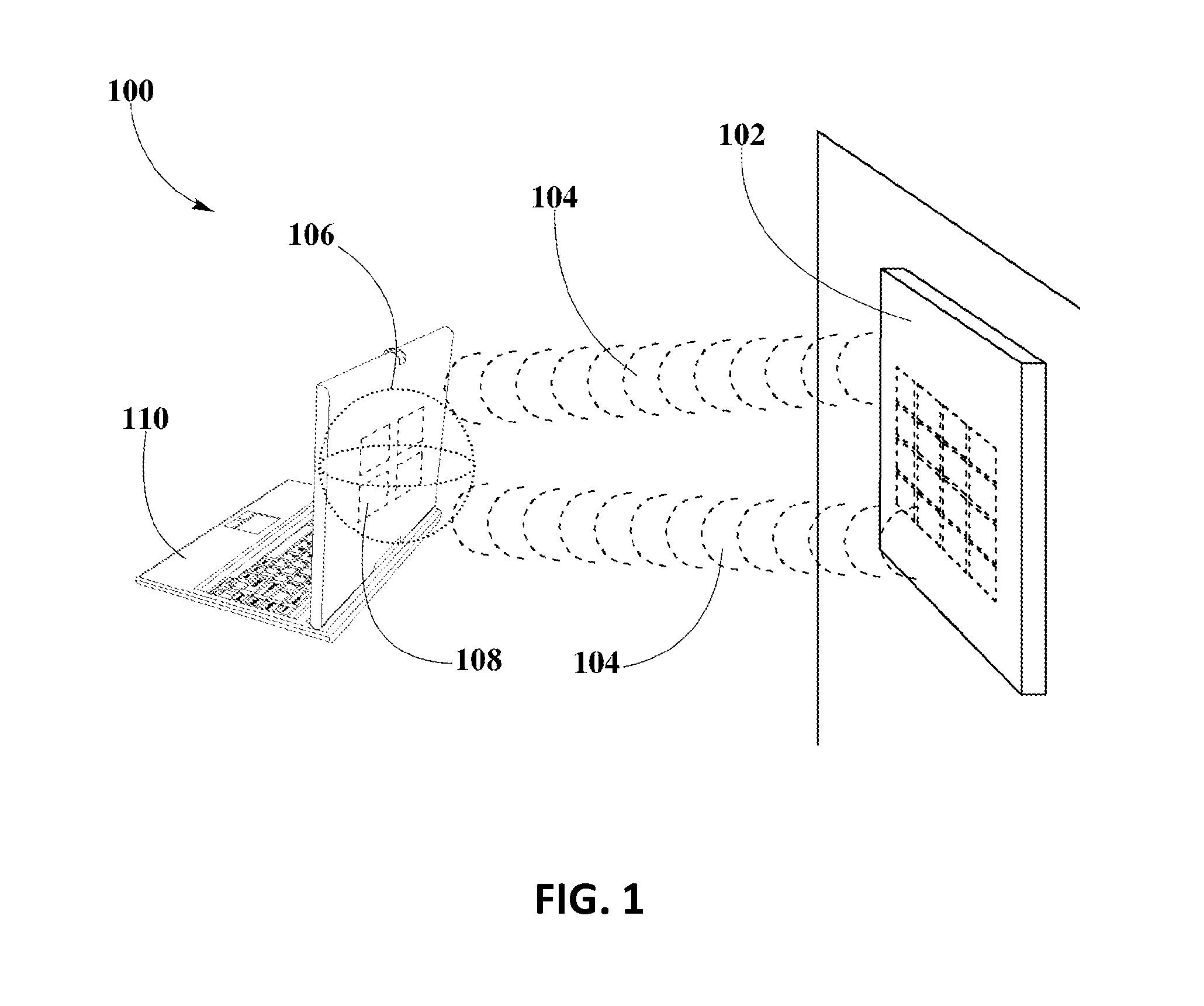
[0028]“Wireless device” refers to any electronic device able to communicate using one or more suitable wireless technologies. Suitable devices may include client devices in wireless networks and may be part of one or more suitable wireless technologies, including Wi-Fi and Bluetooth amongst others.

[0029]“Wireless transmitter” refers to a device, including a chip which may generate two or more RF signals, at least one RF signal being phase shifted and gain adjusted with respect to other RF signals sub...


PUM


Abstract

Synchronous rectifier circuit topologies for a wireless power receiver receiving a supply of power from a wireless transmitter are disclosed. The synchronous rectifier circuit topologies include a half-bridge diode-FET transistor rectifier for rectifying the wireless power into power including a DC waveform, using a control scheme that may be provided by a delay-locked loop clock, or phase shifters, or wavelength links to control conduction of FET transistors in the synchronous rectifier circuit topology, and maintaining a constant switching frequency to have the diodes, coupled to FET transistors, to allow current to flow through each one respectively at the appropriate timing, focusing on high conduction times. The synchronous rectifier circuit topologies may enable power transfer of high-frequency signals at enhanced efficiency due to significant reduction of forward voltage drop and lossless switching.

Description

CROSS-REFERENCE TO RELATED APPLICATIONS[0001]The present disclosure is related to U.S. non-provisional patent application DWV-3DPF-010 entitled “Methodology for Pocket-forming”; DWV-3DPF-015 entitled “Method for 3 Dimensional Pocket-forming”; DWV-3DPF-027 entitled “Receivers for Wireless Power Transmission”; DWV-3DPF-029 entitled “Transmitters for Wireless Power Transmission” invented by Michael A. Leabman; and ENG-SYHW-001 entitled “Enhanced Receiver for Wireless Power Transmission” invented by Jason Petras and Michael A. Leabman, each of which is incorporated herein in its entirety.BACKGROUND[0002]1. Field of the Disclosure[0003]This disclosure relates generally to wireless power transmission, and more particularly to a half-bridge synchronous rectifier design using circuit topologies with low power loss characteristics for a wireless power receiver.[0004]2. Background Information[0005]A plurality of electronic devices are powered via rechargeable batteries. Such devices include s...

Claims


Application Information

Patent Timeline
IPC IPC(8): H02M7/25
CPCH02M7/25H02M3/156H02M7/217H02J50/20H02J7/00712H02M1/007H02M7/05
Inventor PETRAS, JASONLEABMAN, MICHAEL
Owner ENERGOUS CORPORATION
Learn More