Apparatus for controlling an internal combustion engine

Inactive Publication Date: 2015-10-22
TOYOTA JIDOSHA KK
View PDF5 Cites 20 Cited by
  • Summary
  • Abstract
  • Description
  • Claims
  • Application Information

AI Technical Summary

Benefits of technology

The present invention solves the problem of delay in activating the catalyst in a vehicle due to the heat transfer from exhaust gas to the turbocharger. The invention proposes a method of oscillating the air-fuel ratio between lean and rich combustion to accelerate the reaction of gases on the upstream of the turbocharger, thus rapidly increasing the temperature of the turbocharger and suppressing the delay in activating the catalyst. The wastegate valve is controlled in response to the reaction state to effectively employ the thermal energy generated during the reaction for warming up the catalyst. The invention also suggests detecting the reaction state based on the temperature or fluctuation of the air-fuel ratio in exhaust gas. These measures enable simple and effective suppression of the delay in activating the catalyst.

Problems solved by technology

However, according to the apparatus proposed in Japanese Patent Laid-Open No. 2008-095542, when the wastegate valve is closed and the dither control is started after the catalyst temperature has reached the predetermined level, immediately afterwards, a delay occurs in the activation of the catalyst because the heat of the exhaust gas is transferred to the turbocharger, and unburned components, such as CO and HC, are slipped out through the catalyst, so that emission is degraded.
Further, for the apparatus proposed in Japanese Patent Laid-Open No. 2007-332867, there is no means provided to solve a problem caused by the heat being transferred to the turbocharger when the catalyst is to be activated by starting dither control.

Method used


Image

  • Apparatus for controlling an internal combustion engine
  • Apparatus for controlling an internal combustion engine
  • Apparatus for controlling an internal combustion engine

Examples


first embodiment

[General Arrangement]

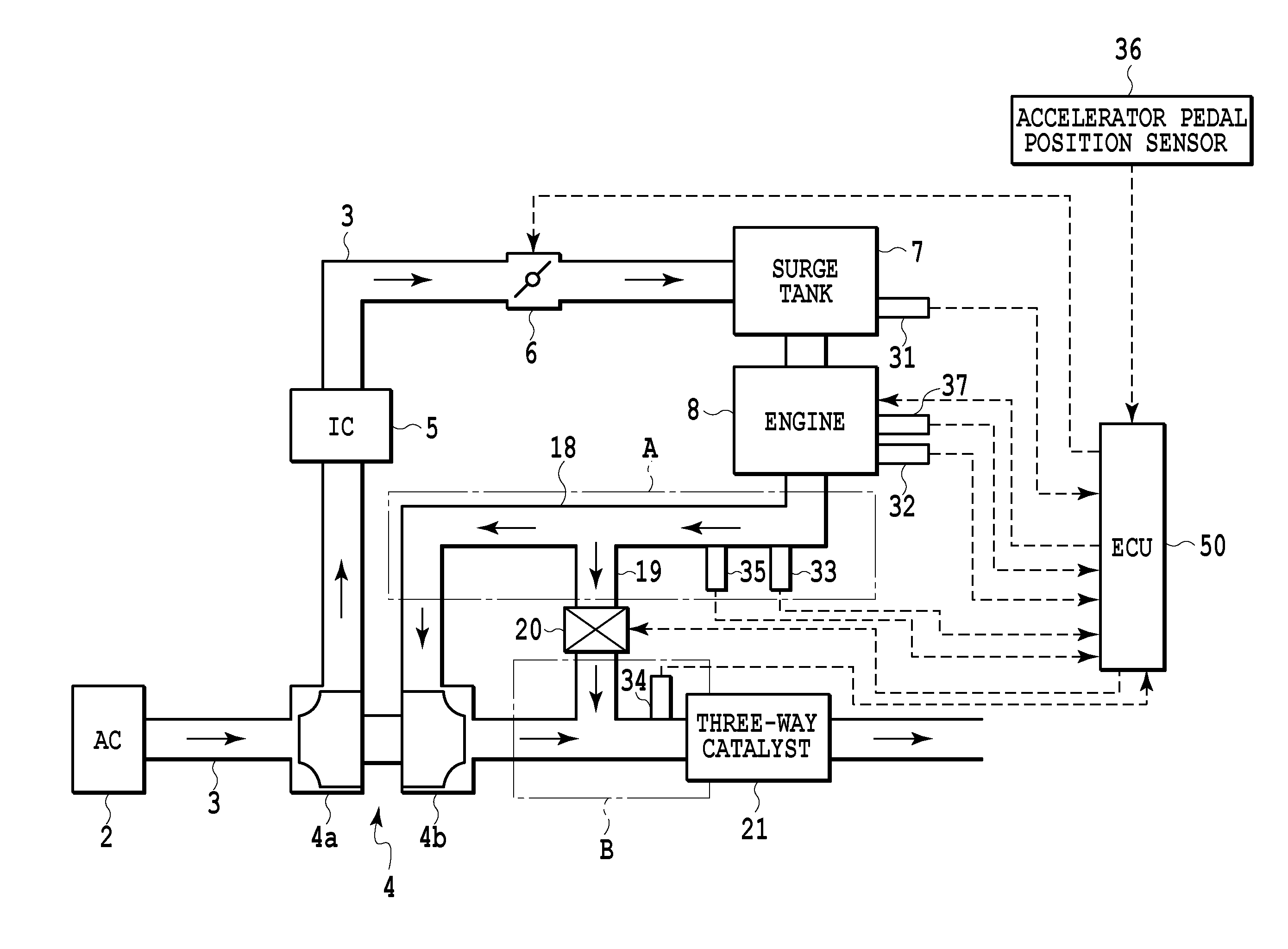
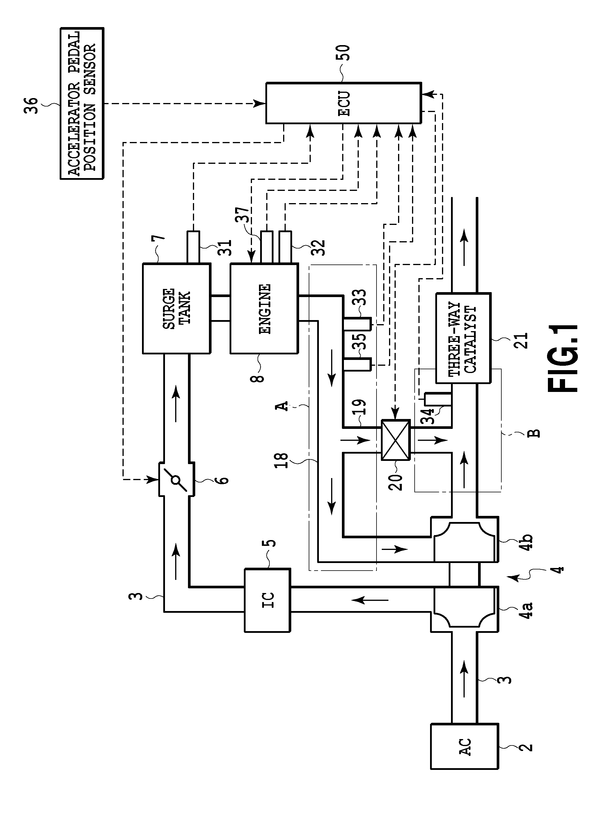
[0029]FIG. 1 is a schematic diagram showing the arrangement of a vehicle, for which a control apparatus for an internal combustion engine according to a first embodiment of the present invention is applied. In FIG. 1, solid line arrows indicate the flow of gas, and dashed line arrows indicate input / output of signals.

[0030]In FIG. 1, a vehicle includes an air cleaner (AC) 2, an intake passage 3, a turbocharger 4, an intercooler (IC) 5, a throttle valve 6, a surge tank 7, an engine (internal combustion engine) 8, an exhaust passage 18, a bypass passage 19, a wastegate valve 20, a three-way catalyst 21, an intake air pressure sensor 31, a water temperature sensor 32, an oxygen sensor 33, an A / F sensor 34, an exhaust gas temperature sensor 35, an accelerator pedal position sensor 36, a crank angle sensor 37 and an ECU (Electronic Control Unit) 50. The engine 8 is an in-line, four-stroke, reciprocating gasoline engine.

[0031]The air cleaner 2 filtrates air (intake air...

second embodiment

[0071]A second embodiment of the present invention will now be described. In the first embodiment described above, the wastegate valve 20 is set to the closed state after an afterburning determination has been made (Yes at S100) (S110). Instead of this configuration, a reaction state of rich gas with lean gas upstream of a turbocharger 4 may be detected, and during the A / F oscillation, the wastegate valve 20 may be set at arbitrary opening degrees in the middle of the degrees for the open state and the degrees for the closed state. Further, means for detecting the reaction state may employ a fluctuation of the air-fuel ratio in exhaust gas to detect the reaction state. The second embodiment employs these points as characteristics. Since the mechanical arrangement for the second embodiment is the same as that for the first embodiment, a detailed explanation for the corresponding components will be omitted by providing the same reference numerals.

[0072]The control performed in the sec...


PUM


Abstract

A control apparatus for an internal combustion engine is provided. The control apparatus includes a turbocharger, a bypass passage, a wastegate valve, a catalyst device and a controller. The controller sets the wastegate valve to a closed state in a case where a warm-up execution condition is established, and performs A / F oscillation for increasing or decreasing the fuel injection amount so that lean combustion and rich combustion are alternately performed in a case where the temperature in the exhaust passage upstream of the turbocharger is beyond a predetermined reference value.

Description

CROSS-REFERENCES TO RELATED APPLICATIONS[0001]This application claims the benefit of Japanese Patent Application No. 2014-084730, filed Apr. 16, 2014, which is hereby incorporated by reference wherein in its entirety.BACKGROUND OF THE INVENTION[0002]1. Field of the Invention[0003]The present invention relates to a control apparatus for an internal combustion engine, and relates particularly to an apparatus that has a function for controlling a fuel injection amount in order to accelerate warm-up of a catalyst.[0004]2. Description of the Related Art[0005]Conventionally, immediately after cold start of an internal combustion engine, a fuel injection amount is controlled in order to rapidly raise the temperature of a catalyst used for exhaust emissions control until an activation temperature is reached. According to an apparatus disclosed in, for example, Japanese Patent Laid-Open No. 2008-095542, a wastegate valve located along a bypass passage used for bypassing a turbocharger is ope...

Claims


Application Information

Patent Timeline
IPC IPC(8): F02B37/18F01N3/28F02D41/04F01N13/00F01N9/00
CPCF02B37/186F01N13/008F01N2900/1404F02D41/04F01N3/28F01N9/00F02D41/025F02D41/0255F02D41/1475F02D37/02F02D41/0007F02D2200/0802F02B37/18Y02T10/12
Inventor KORENAGA, SHINGO
Owner TOYOTA JIDOSHA KK
Why Eureka
Try Eureka